ABSTRACT
Ti6Al4V alloy combines mechanical strength, deformability, excellent fatigue and corrosion resistance and high strength to weight ratio. Furthermore, the mechanical behavior remains excellent at high temperature. Such characteristics make this material attractive for numerous applications (structural, aerospace and naval) because of recent improvements in welding techniques (laser, hybrid laser/MIG) that allow realizing high quality titanium welded joints. However some problems related to the welding, as deteriorated material properties, residual stresses and distortions, need further investigations.
This paper presents a detailed study on residual stresses of Ti6Al4V butt plates welded by laser or hybrid laser/MIG process. Residual stresses were measured by hole drilling method using electrical strain gage rosettes bonded at different position, in order to evaluate magnitude and distribution of residual stresses along the cord. Residual stresses curves obtained for each type of joint and each welding technique are presented and discussed in terms of transversal residual stresses. Residual stresses were also measured at surface by means of X-ray diffractometer.
The aim of this work is to present experimental data related to welding processes in order to confirm the validity of currently procedures or improve them.
INTRODUCTION
Ti6Al4V is a biocompatible material that can be used in different applications such as chemical, aerospace, naval and biomedical engineering.
Welding technology is widely used to assemble metal parts because of high productivity and flexibility [1]. One of the concerns associated with welding Ti-based alloys results from their poor thermal conductivity, which leads to the creation of a steep thermal gradient across the weld region, and hence results in high residual stresses. Ti-based alloys are also susceptible to the formation of porosity and inclusions (e.g. hard alpha) when welded in the presence of hydrogen, oxygen, nitrogen, or carbon contamination, which results in reduced mechanical properties. Accordingly, in fusion welding processes, argon shielding is customarily used to avoid any contamination [2]. Because of its high level of specific power and the limited area involved, laser technology appears to be a promising solution. The laser beam sources of the new generation are capable of producing deep and narrow seams. However, the laser welding process leads to a non-uniform temperature distribution and associated thermal strains, which generate residual stresses due to melting and subsequent cooling of the weld and surrounding material [3].
Steen [4] showed that an addition of electric arc to the laser beam used for welding and cutting could decrease the needed power of laser with respect to the case when only laser is used for welding. This technique combines the best characteristics of both laser and arc welding processes, acting simultaneously in the same process zone [5]. Subsequently, the laser-based hybrid welding technology development was initiated not only at the academic level but also at industrial level, from shipbuilding to automotive production. The advantages of the hybrid welding technique compared to pure laser welding or arc-welding are well known and include an increase in (a) the welding speed, (b) the weldable material thickness, (c) the gap bridging ability, and (d) the welding process stability and efficiency [6]. In particular, laser-arc hybrid welding offers many advantages for heavy industrial applications involving thick-walled materials as it enables full penetration weld of thick plates without the need of multiple passes and at that reduces welding after works such as cutting for adjustment and fairing at the assembly stage. Hybrid welding improves productivity by two to four times as compared to the conventional arc welding [5]. In addition, in the fusion zone of hybrid laser-arc welding, equiaxed grains exist, whose sizes are smaller than that obtained from arc welding but larger than those from laser beam welding. Welding process unavoidably involves a stage of residual stress in the welded structure that could lead to some problems in terms of dimensional stability and structural integrity. Because of the variety of factors involved in welded parts, it is very difficult to predict and control residual stresses caused by welding. Tensile stresses, such as welding residual stresses, may have a significant effect on corrosion, fracture resistance and fatigue performance, so that a reduction of these stresses is generally desirable [7]. As the welded part of a component is often the least resistant to fatigue, stress-corrosion and fracture, numerous experimental methods have been developed and applied to research in the field of residual stresses caused by welding [3]. In view of these aspects, the aim of this research is relating residual stresses to welding technique and type of joint. In this paper, we report experimental hole drilling method measurements on Ti6Al4V butt plates produced by means of laser or hybrid laser/MIG welding process. Electrical strain-gage rosettes have been bonded at different position, in order to evaluate magnitude and distribution of residual stresses along the cord. The focus is on the value of residual stresses normal to the weld cord. Residual stresses were also measured at surface by means of X-ray diffractometer in order to discuss these concentrated values of stress with data obtained by HDM.
MATERIALS AND WELDED JOINTS PREPARATION
Titanium alloys can be classified as a alloys (hexagonal crystal structure), p alloys (body centered cubic structure) and a-p alloys. Alpha alloys (titanium grade 2) are characterized by satisfactory strength, toughness and weldability, but are less forgeable than p alloys. Properties of a-p alloys (titanium grade 5) can be controlled through heat treatment. Ti6Al4V is a a-p alloy where aluminum is a a – stabilizing element and vanadium is a p – stabilizing element. The final microstructure and mechanical properties depend on the initial temperature of heat treatment and on cooling time [8]. Table 1 reports the chemical composition of tested material. Table 2 summarizes some mechanical and physical properties of titanium with respect to comparable steel, as indicated in data sheet of manufacturers (tensile ultimate strength ou, yield strength oy, modulus of Young E). Density, coefficient of thermal linear expansion (CTE) and thermal conductivity in titanium are quite low with respect to steel [9].
Four types of welded plates have been considered as indicated in Table 3.
|
Ti |
N |
C |
Fe |
O |
Al |
Sn |
Zr |
Mo |
V |
|
|
Ti6Al4V |
90 |
0.05 |
0.1 |
0.3 |
0.2 |
6 |
- |
- |
- |
4 |
Table 1 – Chemical composition
|
Oy [MPa] |
Ou [MPa] |
E [GPa] |
Hardness Vickers |
Density [g/cc] |
CTE [^m/m-.°C] |
Thermal conductivity [W/m.K] |
|
|
Ti6Al4V |
1100 |
1200 |
114 |
396 |
4.43 |
8.6 |
6.7 |
|
AISI4340 |
862 |
1282 |
205 |
384 |
7.85 |
12 |
44.5 |
Table 2 – Mechanical and physical properties
|
|
Thickness [mm] |
Length x Width L[mm] x W[mm] |
Welding technique |
Type of joint |
|
Plate 1 (Ti236) |
3 |
400 x 450 |
Hybrid |
butt |
|
Plate 2 (Ti239) |
3 |
400 x 450 |
Hybrid |
butt |
|
Plate 3 (Ti233) |
3 |
400 x 450 |
Laser |
butt |
|
Plate 4 [9] |
3 |
400 x 380 |
Laser |
butt |
Table 3 – Welded plates tested
Before welding, titanium plates are subject to heat treatments and subsequent cooling in air. Titanium plates are accurately lapped and edges are chemically etched. Then, both laser welding (LBW) and hybrid laser/MIG (HYB) are executed without gap between the welded plates. Nd-YAG laser and CO2 laser are utilized respectively. During welding operations, all plates are constrained in 3 points in order to avoid the opening of the junction. Weld traces are then crossed out by the next welding passage. Both in HYB and LBW, the molten welded metal area has been shielded with a specific device and inert gas until 700°C in order to avoid contamination from the air and absorption of impurities.
|
Welding type |
LASER |
|
Equipment |
Laser ND-YAG -HAAS HL 2006D |
|
Focal lens [mm] |
f=100 |
|
Device for Gas for plasma suppression |
standard nozzle f=6mm; special nozzle: |
|
Scarpeta TINEA |
|
|
Gas for plasma suppression |
Elio 4.8, delivery capacity 25 Nl/min |
|
Gas for protection |
Ar 5.0 |
|
Edge preparation |
right (gap 0) |
|
Power of laser beam [W] |
1600 |
|
Feed velocity [m/min] |
3 |
Table 4 – Process parameters of the laser welded plates
|
Welding type |
HYBRID (LASER+MIG) |
|
Laser CO2 power [W] |
3000 |
|
MIG power [W] |
7200 |
|
Distance laser-MIG [mm] |
0 |
|
Welding velocity [m/min] |
2 |
|
Wire velocity [m/min] |
4 |
|
Gas for plasma suppression |
He |
|
Gas for protection |
Ar |
Table 5 – Process parameters of the hybrid laser -MIG welded plates TEST METHOD
The Hole Drilling Method (HDM) is the most widely used technique for residual stress measurement. The principle involves introduction of a small hole (1.8 mm diameter and up to about 1.0 mm depth) at the location where residual stress is measured. Due to drilling of the hole, residual stresses are relieved and the corresponding strains on the surface are measured using strain gauges bonded around the hole. From these measured strains, residual stresses are calculated using appropriate calibration constants derived for the particular type of strain gauge rosette used. The procedure for residual stress measurement using hole drilling is described in ASTM standards with designation E837-08 [10]. In most practical cases, the residual stresses are not uniform with depth. The incremental hole drilling method is an improvement on the basic hole drilling method, which involves carrying out the drilling in a series of small steps, which improves the versatility of the method and enables stress profiles and gradients to be measured. A high-speed air turbine and carbide cutters are used to drill the hole without introducing any further machining stresses and thereby modifying the existing stress system. The strain data at pre-determined depths are precisely acquired. Different stress calculation methods are used to arrive at the residual stress system from the measured strains. The major techniques in vogue are uniform stress, power series and integral methods. In any case, a meticulous measurement practice is crucial to obtaining good quality strain data and the application of the correct analysis method to the relieved strain data can provide accurate assessment of the residual stress field. In this case, in order to consider the variation of the residual stresses measured through the thickness, the power series method has been used.
The X-ray diffractometer method (XRD) is the most common non-destructive method to determine the surface residual stress in crystalline materials. XRD is accurate, but it is limited by the fact that only information is obtained about a relatively thin surface layer.
The XRD-sin2y technique was developed from the theories of crystallography and solid mechanics [11]. Given the limited penetration of X-rays in solid surfaces, what the XRD-sin2y technique measures is the surface residual stress in a depth of up to a few micrometers.
The XRD-sin2y stress measurement starts from XRD scans at a series of fixed incident angles and over a predefined diffraction angle. In each obtained scan, the chosen diffraction peak position has to be accurately determined, i.e. the 29 value has to be measured from a very broad and sometimes irregularly shaped peak (Fig. 1). The obtained 29 values are then used to perform the linear regression in order to obtain the slope and intercept values to be used for the stress calculation. The accuracy of the XRD-sin2y residual stress measurement depends on the minimization of various measurement errors derived from several sources, e.g. the material to be measured, the instrument setup and the data processing. In terms of the tested materials, it is often the case that the surfaces to be measured are not ideally flat, may contain coarse crystalline grains, strong texture, high density of lattice defects and an in-depth stress gradient. Consequently, the diffraction peaks obtained in such materials have different scales of broadening, roughening and asymmetry.
Figure 3 shows the in-plane stress o $ with respect to the two principal stress components o 1 and o 2. When a X-ray beam hits the sample surface at an incident angle Q, those grains, with their (hkl) lattice planes meeting the Bragg diffraction condition and having an off-axis angle y with respect to the sample surface normal, emit a diffraction X-ray beam at a diffraction angle 29. Then the d-spacing d$y of the (hkl) lattice plane is measured. The principal formula for the XRD-sin2y stress measurement can be written as:
where d0 is the unstressed lattice parameter, E and v are the Young’s modulus and the Poisson’s ratio normal to the (hkl) orientation of the material respectively, and y is the angle between the diffraction vector and the normal to the surface.
Assuming o$=o1=o2 when the in-plane stress is independent of the orientation (for a state of equi-biaxial stress) the equation describing the stress dependence of the lattice parameter, d$y is related by the equation:
Then Eq. (2) can be treated as a linear function Y=aX+b where:
Therefore after making a series of XRD scans covering a known Bragg 29 at fixed glancing angles Qi (for i=1, 2, 3, etc.), the Bragg diffraction half angle 9i can be measured in each diffraction peak and the associated off-axis angle yi is calculated according to the relation yi=9i – Qi. The obtained 9i and yi are subsequently used to calculate the data group {Xi, Yi} according to Eq. (3), from which a linear regression processing of Eq. (2) is used to obtain the value of the constants a and b. Finally the in-plane stress o, as well as the strain free lattice d-spacing d0, can be obtained from the relations d0=b and o=a/d0 respectively.
Fig. 1 – A schematic diagram showing the set-up of the XRD-sin2y in-plane stress measurement [12]
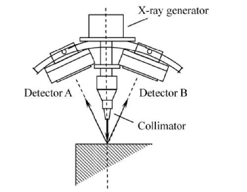
The sin2y method of XRD has utilized to measure the residual stress of welded plates by XSTRESS 3000 equipment [11], in which TiKa radiation (X = 2.2909 A) is used as X-ray source. Fig. 2 shows schematic of X-ray diffractometer.
Fig. 2 – Schematic of X-ray diffractometer.
Residual stress measurement has been performed on the transversal direction to the weld cord of butt welded plates. The collimator with 1 mm illuminated spot size has been used and the exposure time has been set at 90 sec to ensure the adequate intensity. The operation voltage and current were 30 kV and 6.7 mA. The 110-diffraction of titanium with the diffraction angle of 137.4° has been analyzed. During the stress measurement, y of 0°, 19.3°, 27.9° and 35° have been selected to plot d-sin2 y curves on both positive and negative y range. Considering the texture effect on the stress measurement, a y oscillation with ±3° has been used during the measurement. Indeed, to give reliable values of residual stress, measurements have been replicated on the same points.
The experimental investigation is focused on residual stress measurements. Residual stress and distortion are unavoidable in welding and their effects on global strength of structures cannot be disregarded [13]. Welded plates studied in this work present a very slight misalignment: about 0.03° for LBW and about 0.33° for HYB. The extension of heat-affected zone could give indication on the severity of welding thermal cycle. Typically, LBW has a very narrow heat affected zone (0.5 mm for plates 3 and 4) with respect to HYB plates (2 mm for plates 1 and 2) [9].
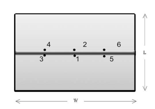
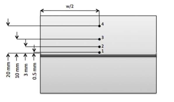
Geometry of welded plates and locations of residual stress measurements are shown in figures 3-4.
Fig. 3 – Geometry of welded plates and location of drilled holes in HDM
Fig. 4 – Geometry of welded plates and location of XRD measurements
Test plan is summarized in Table 6: residual stress on both hybrid and laser welded plates are measured by means of HDM and XRD. Location of measurement points is indicated in fig. 3 and 4. Strain gage rosettes are bonded very close to the weld cord, with the hole at 1 mm from the weld line.
|
Welding |
Residual stress |
Location of residual |
|
|
|
technique |
measurement |
stress measurement |
|
Plate 1 (Ti236) |
Hybrid |
HDM |
As indicated in Fig. 3 |
|
Plate 2 (Ti239) |
Hybrid |
XRD |
As indicated in Fig. 4 |
|
Plate 3 (Ti233) |
Laser |
XRD |
As indicated in Fig. 4 |
|
Plate 4 [9] |
Laser |
HDM |
As indicated in Fig. 3 |
Table 6 – Test plan
![A schematic diagram showing the set-up of the XRD-sin2y in-plane stress measurement [12] A schematic diagram showing the set-up of the XRD-sin2y in-plane stress measurement [12]](http://what-when-how.com/wp-content/uploads/2011/07/tmpA168_thumb_thumb.jpg)


