ABSTRACT
The traditional contour method measures a cross-sectional map of residual stress by cutting a body carefully in two and measuring the surface contour. This talk will present two new advances, both motivated by the measurement of a single challenging part. The first advance is a two-step process for measuring hoop stresses in cylinders. In the first step, a cut is made to split the cylinder (from an "o" cross-section to a "c"). That cut releases a bending moment which would otherwise causes errors in the contour measurement. The amount the cylinder springs open or closed is measured and used to determine the bending moment stresses. In the second step, the traditional contour method is applied: a cut is made to measure the remaining hoop stresses on a cross section normal to the hoop direction. The total residual stresses are given by superimposing the bending stresses and the remaining stresses. In this paper, the two-step process is applied to measuring the stresses in a circumferential welded cylinder of depleted uranium and is compared to neutron diffraction results. The welded cylinder also contains a further measurement complication. The weld was only partial penetration, leaving part of the joint unwelded. The measured surface contour therefore had a discontinuity across the joint. Proper handling of the surface discontinuity is presented.
INTRODUCTION
The contour method is a relatively new method for measuring residual stress [1-3]. In the contour method, a part is carefully cut in two along a flat plane causing the residual stress normal to the cut plane to relax. The contour of each of the opposing surfaces created by the cut is then measured. The deviation of the surface contours from planarity is assumed to be caused by elastic relaxation of residual stresses and is therefore used to calculate the original residual stresses. One of the unique strengths of this method is that it provides a full cross-sectional map of the residual stress component normal to the cross section. The contour method is useful for studying various manufacturing processes such as laser peening [4-9], friction welding [5,10,6,11,12] and fusion welding [13-24].
The contour method has been extensively validated and applied for relatively simple geometries such as rectangular (or nearly rectangular) cross section bars and plates (examples above and [25-28]). Other applications involve more complicated cross sections but still prismatic extrusions [29,7,30] such as a railroad rails [31]. Occasionally, the contour method is applied to slightly more complicated geometries but ones that do not require much special effort [32-34].
This paper details a contour method application that involves two geometrical complications that require special attention. The first is the measurement of hoop stresses in a cylinder. The second is a discontinuity in the measured surface contour because of an unbonded butt joint.
Hoop Stresses in Cylinders
Pipes and cylinders are important geometries for residual stress measurement. A notable example is girth (circumferential) welds on piping and pressure vessels. Cracks cause concern for rupture in nuclear power plants [35,36]. To remain in service, such defected components must be demonstrated to be safe against rupture. Residual stresses are a main driver for the growth of cracks and must be known for crack growth and leak-before-break analyses [37-39]. Measurement of those stresses is difficult. Neutron diffraction is the most commonly published technique for measuring internal stresses. However, some components are too thick for neutron measurement and welds are often problematic because of spatial variations in the reference lattice constant caused by chemistry changes in and around the weld [40-42] or the presence of microstresses [42]. The deep hole method [43] has had the most success on very thick components but measures only a 1D stress profile. For all of the reasons, the ability of the contour method to measure a cross-sectional map of hoop stress in a cylinder is important.
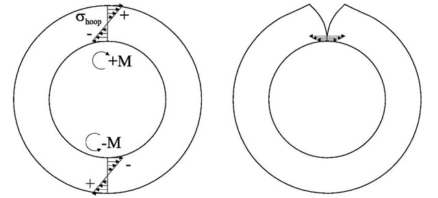
Measuring hoop stresses in a cylindrical geometry requires special attention with the contour method. In simply-connected geometries, residual stresses must satisfy force and moment equilibrium over any cross section. Because the cylinder is a multiply-connected geometry, the residual hoop stresses can have a net bending moment through the thickness of a ring, see Fig. 1. Even for axisymmetric stresses, the moment is balanced by the opposite moment at any other cross section. For a contour method measurement of hoop stress, a radial cut is used. During cutting, because of the bending moment, excessive stresses build up at the cut tip and can cause plasticity. Since the contour method assumes elastic stress relaxation, errors can result and have been observed with the contour method [3] and similarly with the crack compliance method [44].
Fig. 1 Residual hoop stresses in cylinders can have a net bending moment (left), which can cause excessive stresses at the cut tip (right) when making a contour method measurement of hoop stress.
Discontinuity
Butt joints are often joined using only a partial penetration weld for several reasons. A partial penetration joint is often used for cost and simplicity reasons when the strength of a full penetration weld is not required. Other times, especially in pipes in cylinders, partial penetration is used to protect more delicate inner layers from heating or to maintain geometric tolerances inside the structure.
When a weld joint that includes an unfused portion is cut for a contour method stress measurement, the two sides of the unfused joints may deform such that there is a discontinuity in surface height on the cut surface. A conventional analysis of contour method data would involve smoothing and not allow a discontinuity. To achieve accurate results, the discontinuity must be properly preserved during data processing.
EXPERIMENTAL
Residual hoop stresses were measured in a cylinder with a partial-penetration weld butt-joint. The stresses measured with the contour method were recently compared with neutron diffraction measurements [45]. Space limitations in that paper prevented the presentation of details regarding the contour method measurements, which are detailed in this paper. The neutron measurement details are not repeated here.
Specimen
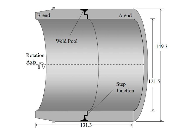
Fig. 2 shows a schematic, drawn approximately to scale, of the welded uranium sample studied in this work. The individual cylinders were as-cast depleted uranium. The sample had the form of a tube 131 mm in axial length with an inner diameter (ID) of 122 mm. At one end, termed the "A" end the outer diameter (OD) was 149 mm but at the opposite end, the "B" end, the outside surface was chamfered down to an OD of 137 mm, resulting in a wall thickness of 14 mm at the "A" end and 8 mm at the "B" end. In this paper, the axial coordinate y is measured relative to the "A" end and the radial or x component is zero at the rotation axis.
Fig. 2. Schematic of the electron beam welded uranium tube. Dimensions are approximately to scale.
The cast cylinders were machine fit at a step joint, as shown schematically in Fig. 2. The weld was a two-pass partial-penetration, autogenous electron beam weld centered at 64.8mm from the "A" end. The first pass, with the e- beam focused, penetrated roughly half of the thickness, bonding the two cast cylinders. The e- beam was then defocused for the second, cosmetic weld pass. The microstructure of the weld is detailed elsewhere [45].
Contour method procedure
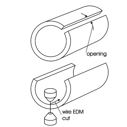
In order to avoid plasticity at the cut tip, a novel, multiple-step variation of the contour method was used to measure hoop stresses over a radial-axial cross-section of the cylinder, see Fig. 3. The first cut severed the cylinder, which relaxed the bending moment. The resulting opening is measured and used to calculate the bending moment stresses. A subsequent cut is used to measure the remaining the remaining hoop stresses with the contour method. Because the bending moment is relaxed prior to the contour cut, plasticity issues are avoided.
Fig. 3. Multi-cut process for measuring cylinders. The amount of opening, measured after the first cut, is used to determine the released bending moment prior to the final EDM cut used for the contour method.
A total of three EDM cuts were made on the uranium tube. Each cut operation used a 100 |im diameter brass wire and "skim cut" settings to reduce the introduction of new stresses [47]. Pairs of scribe lines, separated by about 6mm, were made along the length of the cylinder on the OD. The first EDM cut was made between the scribe lines with the wire oriented axially and translated radially. After unclamping, the relative displacements of the scribe lines were optically measured at 25 mm increments along the length of the tube. The second cut, taken at ~120° counter-clockwise from the first radial cut direction, was used to provide access for the third cut, but has no significant effect on the stresses measured by the third cut. The larger remaining section of the specimen was then measured with the contour method. A stainless steel fixture was machined to securely clamp the part along the ID and OD surfaces. To achieve better cut quality, the wire was now oriented in the radial direction and translated axially to make the cut.
After the final cut, the contours of the opposing surfaces were measured in a temperature controlled environment using a Coordinate Measuring Machine (CMM) with a 0.5 mm diameter ruby touch probe. The surfaces were scanned on a 0.5 mm grid giving about 6800 points per surface.
DATA
As a result of the first cut, the cylinder sprung open by 1.27 ± 0.01 mm uniformly along the length of the cut.
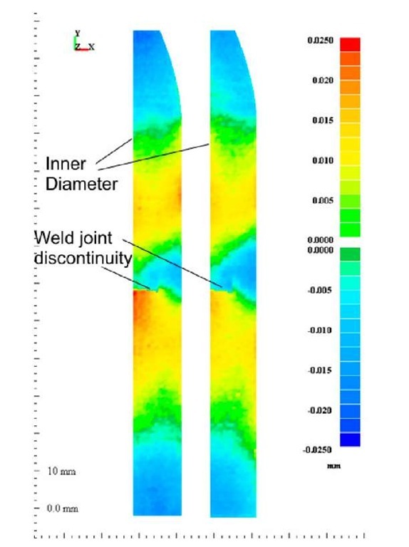
Fig. 4 shows the contours measured by the CMM on the two surfaces created by the third cut. One of the surfaces has been flipped to match the orientation of the other. The peak-to-valley range of the contours exceeds 40 |im. The close agreement between the two contours indicates that the part was clamped well during the cut and the experimental conditions were symmetric [48]. The contours are low in the weld region (right edge, mid height in this figure, see Fig. 2 for weld geometry) as would be expected if tensile stresses were relieved. A height discontinuity is evident cross the joint near the ID, which is mechanically admissible because of the un-joined material associated with the partial penetration weld.
Fig. 4. Surface height contours measured on the two opposing surfaces created by the cut show the expected low region near the weld and also a discontinuity at the unwelded portion of the joint, near the ID.
ANALYSIS
The contour method analysis assumed isotropic elasticity with E=195 GPa, v = 0.21.
A 3D elastic finite element (FE) model was used to calculate the stresses from the contour data. The perimeter of the cross-section was modeled based on the CMM data, and then the surface was meshed with 2D elements. The elements were not joined across the un-joined portion of the step joint. The 2D surface mesh was extruded circumferentially to produce 3D meshes 180 degrees and 120 degrees in extent to analyze the first and third cut data, respectively. The elements were approximately cubes 1.4 mm on a side near the cut surface and graded to be coarser in the circumferential direction farther away. The 180 degree mesh had almost 90,000 bi-quadratic (20 node) reduced integration hexahedral elements. No contact surfaces were used in the un-joined portion of the joint. Observation of the joint after cutting indicated that the gaps between the surfaces were sufficient to prevent contact.
First cut – bending moment
The first FE analysis, using the 180 degree mesh, was used to calculate the bending moment stresses released in the first cut. A symmetry plane was used to constrain one surface and concentrated forces were used to apply a bending moment on the opposite surface, see Fig. 5. The force magnitude was scaled until the surface in the half-symmetry model deformed the opposite amount of the opening observed experimentally.
Fig. 5. Finite element calculation of bending moment stresses. Contour method cut and discontinuity
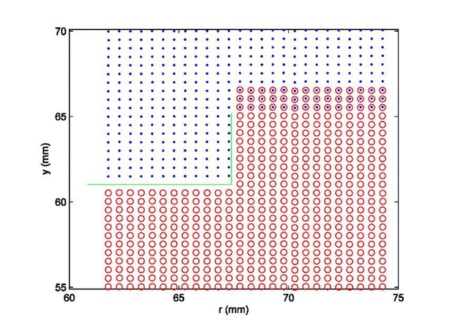
In the contour method, the stresses are calculated in a finite element model by forcing the cut surface into the opposite shape of the measured contour [1]. For this experiment, converting the raw data into a form suitable for stress calculation generally followed standard procedure [3,2], except for some special care because of the discontinuity in the surface contours across the un-welded portion of the joint, see Fig. 4. The two opposing surfaces created by the cut were aligned with each other and then the data was interpolated onto a common grid and averaged. To handle the discontinuity, the surface was divided into two regions on either side of the weld joint with a few mm of overlap only in the part joined by the weld, see Fig. 6. Each region was then smoothed using quadratic bivariate spline fits with an optimal knot spacing determined to be about 5 mm. The two smooth surfaces were then joined together which resulted in discontinuities matching the data but a continuous joint in the weld region where the two regions overlapped.
Fig. 6. Grid points used for fitting surface, zoomed in near weld region of Fig. 4. The green line indicates the unwelded portion of the joint and hence the discontinuity. The red and blue points are the grid points for the two fitting regions, which overlap in the weld region to ensure continuity.
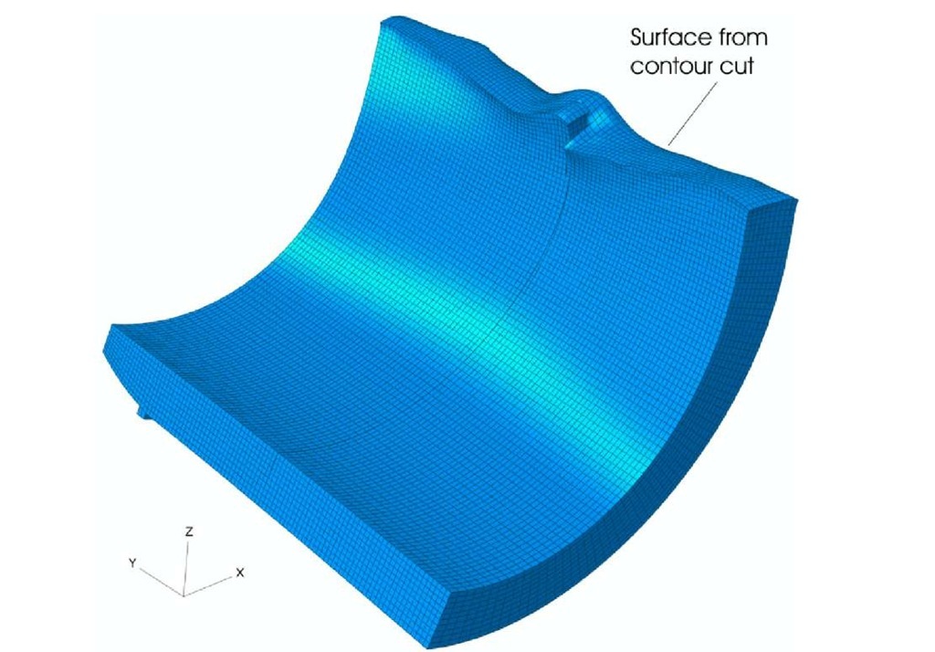
The joined surface was evaluated at nodal coordinates in order to apply displacement boundary conditions to the FE model. Fig. 7 shows the FE model after the displacements were applied to the cut surface to calculate the stresses from the third cut. In this analysis, the other surfaces are unconstrained. The discontinuity across the joint is evident in Fig. 7. For the calculated stresses, a one standard deviation uncertainty of ± 25 MPa was estimated considering random errors in measured contours and uncertainty in the amount of data smoothing [2] but not any systematic errors.
Fig. 7. The finite element model of a section of the cylinder with the cut surface deformed into the opposite of the measured contour. Displacements magnified by a factor of 300.
The stresses calculated from the contour analysis (Fig. 7) were added to the bending moment stresses calculated from the first cut (Fig. 5) to determine the total residual stress.
