ABSTRACT
Residual stress measurements using non-destructive techniques including neutron diffraction and X-ray diffraction are dependent on assumptions made in the analysis. For example, the different stress free reference sample and the presence of precipitates in a material can influence the measured results. Previous residual stress measurement using neutron diffraction technique in a quenched aluminium block revealed that the result can be influenced by the choice of the stress free reference sample. A benchmark method is therefore essential to validate the different measurement techniques.
In this paper, the deep-hole drilling technique was used first as a benchmark technique to validate (1) the measured residual stresses in a water quenched 7449 aluminium alloy block using the neutron diffraction technique, and (2) residual stresses measured using the layer removal technique in a 7449 aluminium plate which was water quenched followed by stretching. Second, the incremental centre-hole drilling technique was used to validate the near surface residual stresses in an aluminium strip measured using the X-ray diffraction technique. The excellent correlations with the benchmark measurement methods validated the different results.
INTRODUCTION
Measurements of residual stresses may be carried out using non-destructive techniques such as the X-ray diffraction (XRD) and the neutron diffraction (ND) or using semi-destructive techniques such as the incremental centre-hole drilling (ICHD) and the deep-hole drilling (DHD) techniques. The XRD and ICHD measurements are limited to only the subsurface whereas the ND and DHD methods can measure deep into components. The ND technique is not readily available and is not portable. Although the ND technique has a penetrative depth limit of about 60mm in most steels, the depth of penetration in aluminium alloys is far greater. However, the presence of strong texture in aluminium alloys can complicate data interpretation [1].
In contrast the DHD technique [2] is portable and can measure residual stresses deep into metal parts, e.g., 430mm deep into steels [3]. Like all other mechanical strain relief techniques, the DHD technique works by measuring distortions when part of the component is machined away. The underlying assumption is that such displacement changes result from elastic unloading. Furthermore, unlike in the ND technique where good result depends on an accurate design of a stress-free reference sample, the DHD technique does not require a stress-free reference sample. However, in components containing high levels of residual stress, elastic-plastic unloading may well occur during material removal, particularly when the residual stresses are highly triaxial. A modification is made to the existing conventional DHD procedure which accounts for the additional change in diametral distortions during the elastic-plastic unloading steps [4].
In this paper, these measurement methods are applied to a 7449 aluminium alloy. This alloy is used for aerospace applications owing to its high strength, stress-corrosion-cracking resistance and toughness. The quenching process is typically used to create high strength in aluminium alloys, but also introduces high residual stresses. These stresses cannot be relieved by thermal relaxation without diminishing the alloys’ favourable mechanical properties. Alternatively, these stresses are relieved by applying a uniform plastic strain. Typically for rolled plate stress relief involves stretching in the rolling direction to strains of 1.5% to 3%. However, the residual stresses remaining after this stress relief process are sufficient to cause distortion during manufacture of aircraft components. The subsequent corrections of the distorted parts to ensure correct fit-up of parts can cost the aircraft parts manufacturing industry tens of millions of Euros per annum [5]. An EU FP6 project called COMPACT consisting of metal producers, aircraft manufacturers and universities was involved in investigating effective ways of reducing and managing the part distortion that arises during component manufacture [6], An accurate characterisation of the residual stress field present in the stress relief alloy was a key step towards establishing a relationship between the stress field and the part distortion resulting from machining.
As part of the COMPACT project University of Bristol was involved in validating residual stresses by benchmarking measurement techniques such as the DHD and the ICHD methods. The samples used in the study are described in the next section followed by a brief description of the residual stress measurement methods. Results are then provided and discussed. Conclusions are drawn about the importance of accurate characterisation and validation of the residual stress present in aluminium alloys.
MATERIAL AND TEST SPECIMENS
Three specimens manufactured from 7449 aluminium alloy were used in the present study. The specification composition of 7449 is given in Table 1. The first sample consisted of a rectilinear forging of dimensions 432mm (L) x 156mm (LT) x 123mm (ST), where L=longitudinal, LT=long-transverse and ST=short-transverse, solution heat treated at 470±5 °C for 5 h followed by immersion quenching into agitated water at less than 20°C. This block, along with two others [7] were forged as a single unit from a 400mm x 145mm x 700mm rectilinear cast slab of 7449 aluminium alloy provided by Alcan, Issoire, France.
|
Si |
Fe |
Cu |
Mn |
Mg |
Cr |
Ni |
Zn |
Ti |
Zr |
|
0.12 |
0.15 |
1.4-2.1 |
0.20 |
1.8-2.7 |
- |
- |
7.5-8.7 |
- |
0.25* |
Table 1 Specification alloy composition of the aluminium alloy 7449 (Al balance, wt%). * Zr + Ti
The second specimen consisted of two notionally identical rolled plates of dimensions 76mm (ST) x 1000mm (L) x 1380mm (LT). The orientations were referenced to the original mother plate from which these plates were sectioned. The mother plate was water quenched to obtain high strength. This was followed by stretching in the rolling direction to 4.4% plastic strain to relieve the quench residual stresses.
The third specimen, also manufactured from 7449 aluminium alloy, consisted of two identical thin (2mm) metal strips of approximate dimensions 400mm x 44mm. These strips were used to study the influence of different machining parameters (cutting speed, feed per tooth, width of cut, depth of cut) on the subsequent part distortions due to the relaxation of residual stresses.
RESIDUAL STRESS ANALYSES
Table 2 summarises the different residual stress measurement methods used on the specimens. A total of five samples with six different residual stress measurement techniques were covered in the present study.
|
Specimen 1 |
Specimen 2 |
Specimen 3 |
|||
|
Specimen description |
Forged quenched block |
Plate 1 (198856B-1) |
Plate 2 (198856BB) |
Strip 1 |
Strip 2 |
|
Residual stress measurement |
Neutron diffraction, Incremental deep-hole drilling |
Layer removal technique |
Standard deep-hole drilling |
X-ray diffraction |
Incremental centre-hole drilling |
Table 2 Summary of the specimens and the residual stress measurement methods.
NEUTRON DIFFRACTION
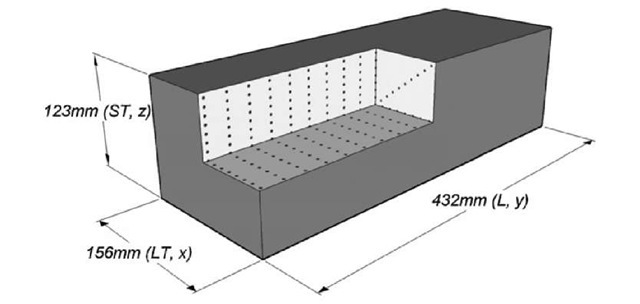
Residual stress measurement deep inside the forged block was carried out using the ENGIN-X instrument at ISIS, Rutherford Appleton Laboratory in Oxford, UK following standard guidelines [8, 9], Fig. 1 shows the measurement locations. As ENGIN-X utilises a spallation neutron source, it is a time-of-flight facility and multiple diffraction peaks were acquired simultaneously. This enabled the lattice spacing a to be obtained directly using a Pawley-Rietveld refinement [10] of a time-of-flight profile encompassing the {111}, {200}, {220}, {311} and {222} matrix peaks. A gauge volume of 4mm x 4mm x 4mm allowed measurements to be completed within the allocated time. The specimen was positioned to permit determination of stresses in the three primary working orthogonal directions of the forging which were assumed to be the principal stress directions. Stress-free measurements (a0) were performed on a small cube sample cut from the corner of a 10mm thick slice which was cut from an end of the block prior to ND measurement. The measured lattice spacing was converted to residual strain, e=(a-a0)/a0. Residual stresses were determined [11] by using Hooke’s law.
As shown in Fig. 1, the x direction corresponds to the LT direction, y to the L, and z to the ST. The bulk elastic modulus E for 7449 aluminium alloy was assumed to be 70 GPa with a Poisson’s ratio v = 0.3.
Figure 1 Neutron diffraction measurement locations denoted by dots in the octant.
STANDARD DEEP-HOLE DRILLING TECHNIQUE
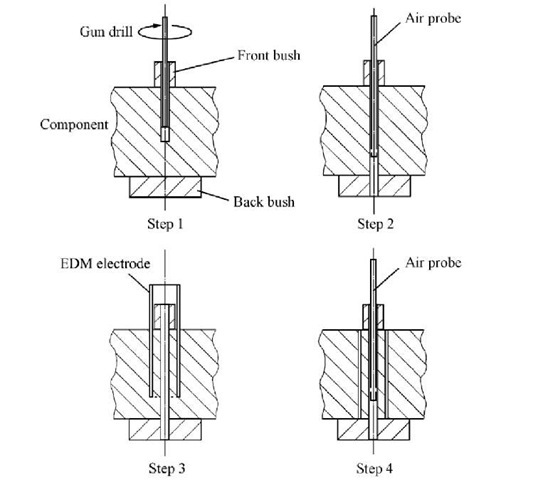
The DHD method determines the through-thickness residual stress distribution in a component by measuring the change in diameter of a reference hole that occurs when a core of material containing the hole is removed by trepanning [2], The steps (Fig. 2) include: (1) A reference hole gun-drilled through the component, (2) Accurate measurements of the initial reference hole diameter taken at a number N, of angles 0 around the reference hole axis and at several increments in depth z, giving d(Q, z), (3) A core of material containing the reference hole trepanned free of the rest of the component using a plunge electric discharge machine, (4) After core removal, the reference hole diameter re-measured to give d’(B, z).
Figure 1 Neutron diffraction measurement locations denoted by dots in the octant. 3.2 STANDARD DEEP-HOLE DRILLING TECHNIQUE
The DHD method determines the through-thickness residual stress distribution in a component by measuring the change in diameter of a reference hole that occurs when a core of material containing the hole is removed by trepanning [2], The steps (Fig. 2) include: (1) A reference hole gun-drilled through the component, (2) Accurate measurements of the initial reference hole diameter taken at a number N, of angles 0 around the reference hole axis and at several increments in depth z, giving d(Q, z), (3) A core of material containing the reference hole trepanned free of the rest of the component using a plunge electric discharge machine, (4) After core removal, the reference hole diameter re-measured to give d’(B, z).
Figure 2 Schematic illustration of DHD method.
The normalised distortions![]() are related to the residual stress components
are related to the residual stress components![]() in the plane normal to the reference hole axis. Elasticity relates the deformations occurring at a hole in a finite-thickness planar-infinite plate subjected to remote planar stress components assumed to be constant through the plate thickness. The unknown stress components are calculated from the measured normalised reference hole distortions using a least squares analysis:
in the plane normal to the reference hole axis. Elasticity relates the deformations occurring at a hole in a finite-thickness planar-infinite plate subjected to remote planar stress components assumed to be constant through the plate thickness. The unknown stress components are calculated from the measured normalised reference hole distortions using a least squares analysis: ![]()
where,
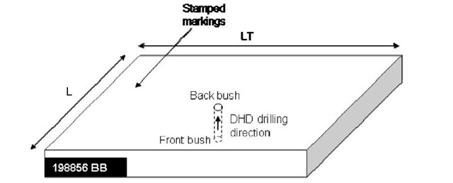
The standard DHD method was used to measure the through-thickness residual stresses in Plate 2 (COMPACT reference 198856BB). The measurement was carried out across the ST direction (Fig. 3). The in-plane longitudinal (oL), long-transverse (0[_j) and shear (aL_LT) residual stress components were obtained. This measurement was used to benchmark the layer removal technique described below that was applied to measure residual stresses in Plate 1 (198856B-1).
Figure 3 Schematic of Plate 2 used in DHD measurement with the measurement direction indicated.
INCREMENTAL DEEP-HOLE DRILLING TECHNIQUE
The recently developed iDHD technique [4] provides an approximate solution to measurements of near yield residual stresses by considering the effects of plasticity during trepanning. The incremental technique relies on obtaining measurements of hole distortions progressively for increments of trepanning depth giving diameters d) where j is the number of interrupted trepanning steps. The changes in diameter are normalised to give normalised distortions
![]() trepan increment. Only a limited set of measurements along the reference hole axis, corresponding to the trepan increments, can be obtained. At each trepan increment the measured hole distortions are introduced into the standard DHD analysis procedure, Eq. 2, to provide stress components at each trepan increment, j,
trepan increment. Only a limited set of measurements along the reference hole axis, corresponding to the trepan increments, can be obtained. At each trepan increment the measured hole distortions are introduced into the standard DHD analysis procedure, Eq. 2, to provide stress components at each trepan increment, j, ![]() and are then compared and combined to create the finalised, discrete measurement results.
and are then compared and combined to create the finalised, discrete measurement results.
The iDHD technique was used to measure the highly triaxial residual stresses in the forged quenched block along the ST direction. This measurement was carried out following the neutron diffraction measurement, and was used to benchmark the ND measurement.
LAYER REMOVAL TECHNIQUE
The layer removal (LR) technique determines the through-thickness residual stress distribution in a component by measuring the change in strain that occurs when layers of material are removed from the component, Fig. 4. Full details can be found in [12], and only an outline of the procedure is given here [13], 
Figure 4 Illustration of the layer removal technique. A strain gauge was used to measure the change in curvature due to successive removal of material layers.
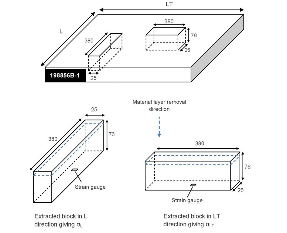
The residual stresses in Plate 1 (198856B-1) were measured using the LR technique. Fig. 5 shows the schematic of the plate with direction of the measurement. Assuming that residual stress were only in the longitudinal (L) and long- transverse (LT) directions as functions of position in thickness, two rectilinear blocks in L and LT directions were removed. Removal of the two blocks modified the stress field in the plate. Typical dimensions of the blocks included the original plate thickness (76mm), width of 25mm and length which was 5 times the thickness (380mm). In each block the residual stresses were assumed to be unidirectional.
Figure 5 Schematic of Plate 1 sample with the measurement direction indicated.
When layers are removed from one side of each of the extracted flat blocks the stresses become unbalanced and the block bends as in Fig. 4. The curvature depends on the original stress distribution present in the layer that has been removed and on the elastic properties of the remainder of the block. By carrying out a series of curvature measurements after successive layer removals the distribution of stress in the original block can be determined. Curvature can be measured using contact methods (e.g. profilometry, strain gauges) or without direct contact (e.g. video, laser scanning, grids, double crystal diffraction topology), allowing curvatures down to about 0.1 mm-1 to be routinely characterised. Finally the stress field in each block is correlated back to the stress field that was in the original plate from which the blocks were extracted.
X-RAY DIFFRACTION TECHNIQUE
X-ray diffraction is a non-destructive method for measuring near surface residual stresses to depths of up to 0.025mm through measurement of a material’s inter-atomic spacing. X-rays have wavelengths on the order of a few angstroms (A), the same as typical inter-atomic distances in crystalline solids. During measurement the component is irradiated with x-rays that penetrate the surface, the crystal planes within the component diffract some of these x-rays according to Bragg’s law. A detector is moved around the component to detect the angular positions where diffracted x-rays are located and records their intensity. The positions of the peaks enable the user to evaluate the stresses within the component.
The near surface residual stresses present in Specimen 3 Strip 1 were measured using the X-ray diffraction technique. The stresses were calculated using the sin2^ method. Electro-polishing was used to measure the residual stresses up to a depth of 0.20mm.
INCREMENTAL CENTRE-HOLE DRILLING TECHNIQUE
The ICHD method [14] was used to measure the near surface residual stress in Specimen 3 Strip 2. Strip 2 was notionally identical to Strip 1 so that the ICHD measured residual stresses could be used to benchmark the XRD measured residual stresses in Strip 1. A strain gauge rosette with an external diameter of 5.13mm was used in conjunction with a hole of diameter 1.8 mm. Measurements were made at non-uniform drill increments starting at fine increment of 0.016 mm, with the released strain on each of the three gauges in the rosette being recorded at each increment. From the relaxed strains the residual stresses were calculated using the integral method and cumulative influence functions derived by Schajer [15]. Following a procedure proposed by Zuccarello [16], the interpolation of Schajer’s cumulative functions was made.
RESULTS AND DISCUSSION
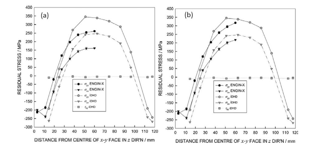
The measurement results are shown in Figs. 6 to 8. Fig. 6 compares the iDHD measured residual stresses with the ND measured in the forged quenched aluminium block along ST direction. Similar trends are shown with compressive residual stresses on the surface and tensile stresses in the interior. As expected, the longitudinal stress component (ow) was higher than the long-transverse stress (oxx) for both measurement techniques. The iDHD measured stress distributions to some extent were symmetric about the x-y face (Fig. 1). This justified the ND measurements limited to an octant. It was assumed that the stresses were symmetric about x-y, y-z and x-z planes. However, the iDHD measurements were significantly more tensile in the interior than the oxx and aw neutron diffraction data (Fig. 6a). This difference is attributed to the choice of stress-free sample used [7]. Re-analysing the ND data, utilising the iDHD core as a stress-free sample, a much improved correlation was obtained as shown in Fig. 6(b).
Figure 6 Comparison of iDHD and ND measured residual stresses along ST (z) direction of the forged quenched block (a) corner cube stress-free sample, (b) DHD core stress-free sample.
A comparison is made between the results obtained from the DHD and LR measurement methods in Fig. 7. For clarity, the longitudinal (L) and long transverse (LT) components of the residual stress distribution are shown separately in Figs. 7 (a) and (b) respectively. An excellent correlation exists between the two measurement methods. This close correlation first, validated the LR technique data using the DHD method and second, confirmed the existence of a uniform residual stress distribution across the thickness in the original mother plate from which these smaller plate samples were machined out.
Figure 7 Comparison of the (a) longitudinal and (b) transverse residual stress distribution in plate samples 198856B-1 and 198856BB, using the layer removal and deep-hole drilling techniques.
Figure 8 compares the near-surface XRD measured residual stresses with those obtained from the application of the ICHD method. Both the trend and the magnitudes of stresses are in excellent agreement. The ICHD stress value at zero depth was erroneous. The stress profile is complemented by the XRD data closer to the surface. The compressive stresses due to machining of the surfaces were measured by both the XRD and the ICHD techniques.
Figure 8 Comparison of near-surface (a) longitudinal and (b) transverse residual stresses in machined strips using the XRD and ICHD techniques.
CONCLUSIONS
This study showed the usefulness of the DHD and the ICHD techniques in validating the ND, the XRD and the LR techniques in samples ranging from a metal strip to forged block, from machining induced residual stresses to water quenched residual stresses. Deep-hole drilling is a relatively robust technique whereas the accuracy of the ND measured result is dependent on the correct choice of stress-free sample. The study showed that the DHD core can be used as a stress-free sample and accounted for the change in lattice parameter across the measurement direction. Fig. 6 illustrated how selecting the correct stress-free sample can improve the accuracy of the measurement.
The close correlation between the DHD and the LR techniques not only validated the LR measured stresses but also the assumptions made in the LR technique. Similarly the ICHD measured stresses validated the XRD data. Fig. 8 also illustrates the complementary nature of the two techniques.
![tmpA-89_thumb[1] tmpA-89_thumb[1]](http://what-when-how.com/wp-content/uploads/2011/07/tmpA89_thumb1_thumb.jpg)
