Abstract
Often unnoticed, elements of thermal energy storage (TES) technology can be found in many common products. As an engineered system, however, thermal storage has matured into an extensively developed technology primarily for commercial comfort and process cooling. Commercial utility rates and the unbalanced cooling demand of this sector make it an ideal candidate for TES. Although water is the predominant storage material, methods of its use vary across a diverse selection of latent and sensible heat equipment types, each with unique performance and operational characteristics. Additionally, systems can be selected and designed to address any fraction of the cooling load in partial or full storage strategies. In manipulating the contribution of chiller and storage to the cooling load, control logic must be consistent with equipment capabilities and capacities, utility energy and demand rate structures, and integrated load requirements.
INTRODUCTION
Thermal energy storage is one of the world’s oldest energy management technologies. For millennia, the mass of shelters has served to moderate extreme temperature excursions by gradually absorbing and releasing heat. And virtually all thermal storage reviews recount the centuries old practice of harvesting ice from rivers and lakes for use throughout the following warmer seasons. Indeed, ice was a major North American export in the 19th century.
One of the unique historical demonstrations of stored cooling occurred on a hot July day in 1620, when the Dutch scientist, Cornelis Van Drebbel, chilled the Great Hall of Westminster Abbey for the benefit of King James I. Van Drebbel reportedly combined snow saved from the previous winter, water, potassium nitrate, and salt in a prescient precursor to the ice cream maker.
There are dozens of more contemporary examples of thermal storage. These include the familiar domestic hot water heater or the household refrigerator icemaker, as well as many lesser known uses, such as in athletic equipment, medical braces and wraps, thermal barriers for fire protection, temperature stabilization of electronic components, and space exploration components.
However, central plant commercial cooling applications have evolved into the most extensively developed sector of thermal storage technology. Professional organizations have published an impressive library of design literature.[1] Equipment and system standards have been developed,[2'3] and manufacturers provide performance data, installation and maintenance instructions, and of course, a wide variety of available products. Other than a broader discussion of storage materials and brief introductions to a selection of additional TES technologies, commercial cooling application and design will dominate the following discussion.
THERMAL STORAGE MATERIALS
Thermal energy is stored by adding or removing heat from a substance. The change experienced by the substance helps define the type of storage system. Although materials such as clathrates and hydrides can store thermal energy through a change in composition, our attention focuses on the more conventional sensible and latent heat properties of materials.
Sensible Heat Storage
When a substance experiences a rise or fall in temperature as heat is added or removed, it is referred to as sensible heat storage. The amount of heat required to raise or lower the temperature of liquid water, its specific heat, is 1 Btu/lb/°F (1 cal/g/°C). That is, 1 Btu will raise or lower the temperature of 1 lb of water 1 °F, an unusually high value. High density, another advantageous property of water, improves volumetric efficiency. The density of water is 62.4 lbs/ft3 (1 g/cm3). Virtually any material can be used for sensible heat storage, but water, concrete, masonry, rock, earth, and ceramic brick are some of the more common. In fact, the structure itself is sometimes used as a thermal storage medium through precooling or solar heat gain.[4'5]
Latent Heat Storage
When liquid water and ice are in thermal equilibrium at 32°F (0°C), the addition or removal of limited quantities of heat does not change the temperature. The addition of heat will change the phase of some of the water from solid to liquid, and the removal of heat will change the phase of some of the water from liquid to solid. This is an example of latent heat of fusion (solid/liquid), the form of latent heat most commonly applied in thermal storage.
Materials employed for thermal storage in this manner are often referred to as phase change materials (PCMs). Water has an extremely high latent heat capacity. It takes the addition or removal of 144 Btu to change the phase of 1 lb of water (80 cal/g) at 32°F (0°C). Water is by far the most widely applied PCM for cooling TES. Its safety, physical properties, high heat capacity, and chemical stability are all important characteristics, but appropriate fusion temperature and negligible cost secure its popularity.
Other latent storage materials have been commercialized or researched over the years for both heating and cooling applications.[6] Sodium sulfate decahydrate (Glauber’s salt), one of many inorganic salt hydrates, was perhaps the most intensely studied and typifies both the promise and pitfalls often encountered. Its low cost, high density (specific gravity 1.46), high latent heat capacity (108 Btu/lb, 60 cal/g), and fusion temperature of 89°F (31.7°C) make it apparently ideal for active (mechanically assisted) and some passive heat storage applications. The performance of salt hydrates has proven difficult to perfect because of the tendency to form undesirable hydrates (e.g., sodium sulfate dihydrate), segregate into separate constituents or supercool (under-cool). Supercooling is the tendency of most liquids to remain a liquid, even as the temperature drops below the fusion point, until some nucleating event precipitates the formation of solid crystals. Once nucleated, the entire mass of material typically rises rapidly back to its customary fusion temperature.
Mixtures of materials at their eutectic, or lowest freezing point concentration, are also effective storage materials, often employed below 32°F (0°C). For example, 23.3% sodium chloride in water exhibits a uniform freezing temperature at — 6°F ( — 21°C). Some salt hydrates and eutectics are available for thermal storage applications that use a variety of proprietary or patented techniques for improving performance. Rolling drum containers, thixotropic mixtures, gelling agents, mechanical stirring, clever container geometry, microencapsulation, and other chemical additives have all been used to prevent segregation and/or induce nucleation.
Other materials include paraffins, fatty acids, and their eutectic mixtures. These are chemically stable, and the ability to tailor the fusion temperature of paraffins by controlling the carbon chain length is an attractive feature. They typically have lower heat capacities, densities, and
thermal conductivities than the water-based materials, and they sometimes experience comparatively high volume changes with phase transition. They are employed in some specialized applications referred to earlier. There have also been several attempts over the years to infuse paraffins into building materials (gypsum wallboard, for instance) to enhance the storage capacity of the building structure.
Although rarely applied, heat transfer to or from many solids at specific temperatures can produce a change in their crystalline structures, another form of latent heat. Some materials will even undergo a series of structural changes (e.g., hexatriacontane) at different temperature plateaus.
TES FOR COOLING APPLICATIONS
Benefits
Many factors encourage the use of thermal storage. Most applications, not only the classic examples like churches, dairies, and theaters that exhibit brief but also intense cooling loads, benefit from substantial reductions in refrigeration equipment and electrical infrastructure. But the principal basis for many TES benefits is energy cost reduction, particularly with the current emphasis on Leadership in Energy and Environmental Design (LEED®) certification.
In addition to the recognized benefits of avoiding the construction of additional generation and transmission facilities, there is also substantial evidence that power generated off-peak is produced more efficiently and with fewer emissions than the peaking power it replaces.[7]
Engineers often install excess capacity to meet unexpected cooling loads or to compensate for mechanical failure, an inefficient and expensive practice. Rather than invest in chiller capacity that will rarely be used, and may produce even higher electrical demand, the same objectives can be achieved with TES while realizing continuing economic benefits. A selection example is included under “System Design.”
Commercial Utility Rates and TES
The commercial customer utility bill is usually comprised of two main components. The first, the energy charge, is based on the amount of electrical energy consumed, or kWh. This energy charge is often reduced during off-peak hours, providing the first incentive for TES. The second component is referred to as a “demand” charge and is based on the rate (kW) at which a customer consumes energy, often for the highest 15-min demand period during on-peak hours. A demand ratchet may extend the impact of high demand to subsequent months. The demand component may be incorporated in an energy charge that is reduced for customers with a flatter electrical demand profile, rather than explicitly identified.
To illustrate, a customer that operates a 100-W light bulb for 10 h will consume the same amount of electric energy as a customer who burns ten 100-W light bulbs for 1 h. However, the customer who consumes that energy over the 10-h period will pay one-tenth of the demand-related utility cost. It is quite common for a commercial customer’s demand charges to contribute more than 50% of the utility bill.
Refrigeration equipment can constitute 40% or more of a commercial building’s peak electric demand, with little or no nighttime cooling load, representing a significant opportunity for energy cost savings with TES. In a very real sense, TES applications that reduce on-peak electrical usage are storing electricity as much as heating or cooling capacity.
Cooling Storage Equipment
Cooling storage devices encompass a wide variety of equipment designs with unique characteristics. Although far from comprehensive, cool storage systems can usually be classified within one of the following groups, as adopted by most manufacturers and ASHRAE.[8] Because storage systems must meet not only the peak instantaneous load (tons), but also provide the integrated cooling capacity over the design period, an essential measure of capacity is the ton-hour (0.0127 GJ).
Ice Storage-HX Coil Builds and Melts Ice
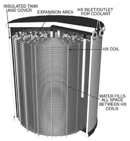
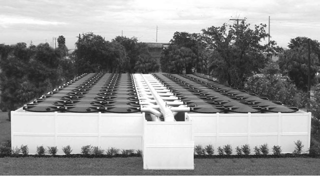
Fig. 1 illustrates a typical design. The complete assembly is usually factory manufactured and provided in thermally insulated, modular units that can be combined to provide the needed capacity (Fig. 2). Cylindrical plastic tanks and rectangular galvanized or stainless steel tanks are available. Plastic tanks provide water containment, while metal tanks include an additional flexible or metal liner to achieve water containment.
An antifreeze solution, usually 25% ethylene glycol/ 75% water[9] and referred to as a secondary coolant, is circulated through the tubular heat exchanger (HX) that is distributed throughout most of the tank’s internal volume. The HX is completely immersed in water that usually occupies about 80% of the tank volume. The remaining space is reserved for the HX and to allow for the expansion of the water as it freezes, decreasing in density by approximately 9%. The expansion of the water into the space above the HX is often used as a measure of ice inventory. Heat exchangers are constructed of plastic, usually polyethylene or polypropylene, or galvanized steel. Copper heat exchangers circulating refrigerants are a more recent development in TES systems with smaller capacities. The spacing between the tubes of the HX is determined by the diameter of the tubes themselves, desired rates of charging (freezing) and discharging (melting), and heat transfer properties of the HX and coolant.
Fig. 1 Modular ice storage tank—charge and discharge through HX.
Note that the water in the tank is not hydronically connected to the building-cooling loop and does not circulate. All of the heat transfer is accomplished by circulation of the coolant through the HX. The HX usually operates as part of the pressurized, closed building loop while the tank itself is at atmospheric pressure.
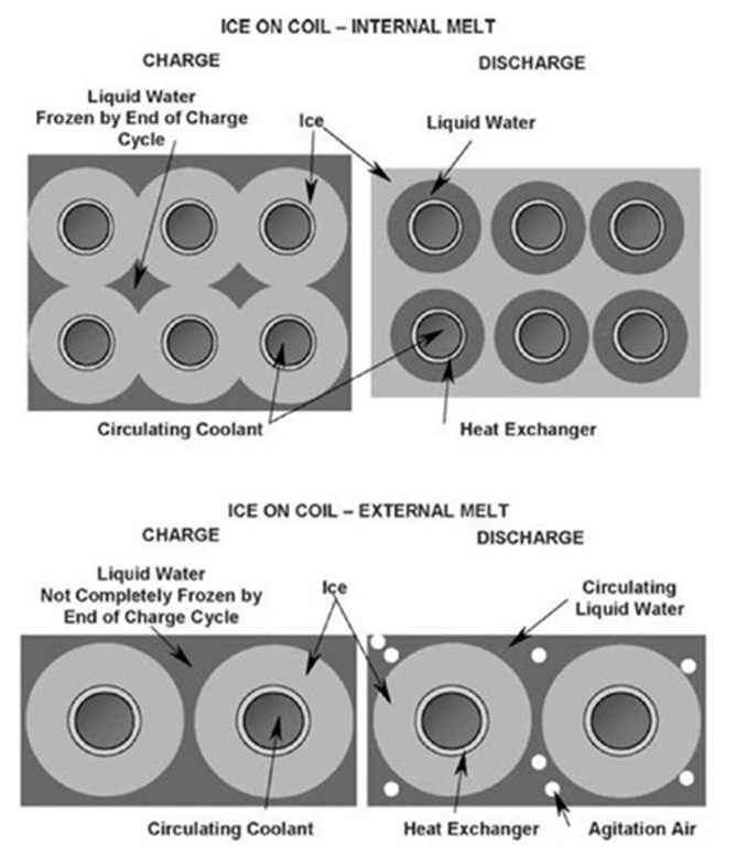
Standard chillers (excluding absorbers) provide the cooling source for freezing the water. During the charging cycle, the chiller cools the secondary coolant to a range of perhaps 20°F (- 6.7°C) to 27°F (- 2.8°C), the lower temperatures reached at the end of the charge cycle. Coolant is circulated through the HX until all the water between the HX tubes is frozen (Fig. 3).
During the discharge, the same coolant is circulated between the cooling load and the storage tank. As the ice surrounding the HX is melted, the 32°F (0°C) liquid water/ ice surface gradually retreats from the HX tube surface (Fig. 3). Therefore, the performance, as reflected in the temperature of the coolant leaving the HX, varies as the ice is melted. Some manufacturers publish charts to describe the variable performance due to this characteristic. This design sometimes employs alternate PCMs.
Ice Storage-HX Coil Builds Ice-Surrounding Water Melts Ice
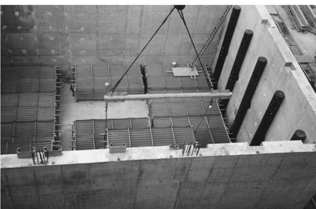
This design shares some features of the internal melt system. Tanks are typically large, site-built, rectangular concrete structures that operate at atmospheric pressure (Fig. 4). The HXs are usually galvanized steel coils, similar to the internal melt coil, but often with wider tube spacing.
Fig. 2 14,000 tn-h, 5000 ft2 modular ice storage system, cooling 1,000,000 ft2 district system.
Fig. 3 Comparison of charging and discharging processes from interior and exterior of ice on coil.
Fig. 4 50,000 tn-h district cooling storage system under construction.
Circulating cold coolant through the HX coils, as in the internal melt design, forms the ice. The major difference is that some liquid water is always left surrounding the ice formed on the HX tubes (Fig. 3). This water is the heat transfer fluid for the discharge cycle, and ice thickness must be carefully controlled to ensure that a flow passage is always available for the circulating water while still achieving the required ice inventory. Because the liquid water is in continuous direct contact with the ice, it is available at consistently low temperatures and high rates of discharge.
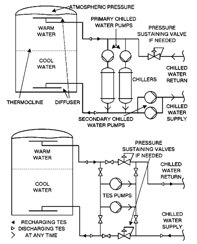
Various methods are used to interface the atmospheric pressure tank with a pressurized building-cooling loop when necessary. For instance, an intermediate HX or pressure sustaining valves (see Fig. 5 for stratified chilled water) can be placed between the two systems.
The velocity of the water within the tank is extremely low. Compressed air is typically distributed through separate piping located under the bottom layer of coils to augment convection and promote even melting and freezing of the ice throughout the often considerable dimensions of the tank.
The refrigeration equipment often contributes to the cooling load during the discharge cycle (see “System Design”), but separation of the chiller coolant (antifreeze solution) from the water loop must be maintained. Rather than simply continue to circulate the coolant through the ice-encased storage coils, improved efficiency can be realized by adding an additional HX between the chiller coolant loop and the building water loop. Sometimes the actual refrigerant is redirected to a separate evaporator where it cools the circulating water.
Although the chiller/coolant method of ice-build has become common, direct expansion or liquid-overfeed of refrigerants, circulated directly through the ice coils, is applied in certain process applications. Water is the only PCM currently used in external melt systems.
Ice Storage-PCM in Sealed Containers or Encapsulated
These systems also employ standard chillers circulating a secondary coolant. However, the PCM, usually water, is contained within sealed plastic containers. Insulated tanks are filled with the containers, and coolant circulates through the tank and around the containers.
Tank configurations include horizontal or vertical cylinders, both pressurized and at atmospheric pressure. The useable volume of PCM depends on the shape of the container, the geometry of the tank, and whether the containers are individually positioned or allowed to pack randomly.
Many container shapes have appeared over the years, including cylindrical tubes and flat trays, but current products are mainly spherical. Additional features, intended to enhance heat transfer or accommodate expansion of the water, include flexible surface geometry, internal voids, or collapsible internal chambers.
Encapsulated systems are available with alternate PCMs, usually salt hydrates and eutectics, but other materials are possible. Supercooling must be prevented by including a nucleating agent or device.
Ice Storage-Harvester
Refrigerant is directed through a collection of vertical plates or tubes while water constantly flows around the external surface. Ice accumulates on the surface, usually to a thickness less than V2 in. Repositioning an arrangement of valves introduces compressed, hot refrigerant gas into the plate. The ice separates from the surface and drops into an atmospheric pressure steel or concrete tank below. This procedure is repeated sequentially over a series of many plates or tubes, so that the process is essentially continuous.
Fig. 5 Chilled water storage piping schematics Top: TES near chiller water plant. Bottom: TES near or remote from chilled water plant.
An alternate approach circulates coolant or refrigerant around an HX that has water combined with a low concentration of glycol flowing on the opposite surface. A combination of mechanical disturbance and the fluid’s reduced tendency to adhere to a surface when frozen eliminate the need for hot gas defrost.
Harvesters are less common in comfort conditioning applications today but are still used in process and industrial applications. As in the external melt design, the direct contact between the circulating water and the ice provides low temperatures and high discharge rates.
Stratified Chilled Water Storage
Chilled water is a sensible heat storage method. The available capacity is proportional to the volume of water and the temperature change it experiences. Cost considerations dictate that the same tank, usually a steel or concrete vertical cylinder, be used to store both the warm water returning from the cooling load and the cold water circulated to the cooling load. It is critical that the warm and cool water are prevented from mixing within the tank.
The preferred approach that has evolved is the simple stratified water system. Because warm water is less dense than cooler water, it will float on cooler water below. However, the density of water at 58°F (14.4°C) is only about 0.05 lb/ft3 (0.8 kg/m3) less than water at 40°F (4.4°C). Maintaining separation is now commonly achieved through careful design of the water diffusers located in the top and bottom of the tank. The goal is to prevent disruption of the stable but delicate density relationship as water enters and leaves.
Two nondimensional flow parameters have usually been accepted as crucial to proper performance. The Froude number is the ratio of inertial to gravitational forces (related to the Richardson number), and the
Reynold’s number is the ratio of inertial to viscous forces. Research, with sometimes inconsistent results, is still evaluating the influences of these and other parameters.1-10-1 Designers, using a combination of analytical and empirical approaches, have nonetheless arrived at a successful design process.
Fig. 5 represents chilled water storage systems part way through a charge or discharge cycle. During charge, flow exits the top of the tank, is cooled by the chiller, and returns to the tank bottom. During discharge, the flow reverses, and water exits the bottom of the tank, is distributed to the load, and returns to the top. Note the area between the warm and cold layers. Known as a thermocline, this short cylinder of water, usually 1-3 ft thick, exhibits a vertical temperature gradient between the cold and warm water temperatures.
Because the maximum density point occurs at 39.2°F (4°C), water is usually cooled to no less than 40°F (4.4°C), and chiller efficiencies are very good during the charging cycle. Additives are sometimes employed to lower the temperature of maximum density and increase the storage capacity. Increasing the system return temperature also expands the storage capacity. However, the water must return to the tank from the cooling system at the design temperature because any reduction represents lost capacity.
Large chilled water storage systems are very economical. Examples include a district cooling application with a 17.6 million gallon (66.6 million liter) tank, 160,000 tn-h total capacity, and a peak discharge rate of 20,000 tn.
Cool Storage System Design
All equipment types require some unique design elements, but an ice storage system will introduce most of the important issues.
Load Profile
The first step is to determine the cooling load profile for the entire design day. In a nonstorage system, the peak load is the primary influence on chiller selection. For storage systems, both the peak load and the total combined load for the design period will determine chiller and storage capacities. Furthermore, chillers may operate at different capacities at different times of the day, and storage performance may vary with system geometry, control sequence, storage inventory, and system temperatures. For this reason, ARI has published a format for specifying operating temperatures, modes, loads, etc. on an hour-by-hour basis.[11]
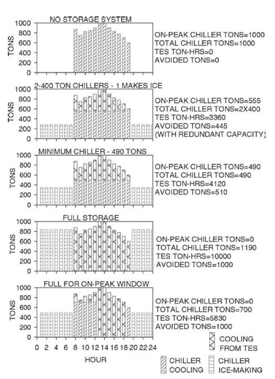
An assumed load profile for a typical office building is depicted in Fig. 6 (top). The peak load is 1000 tn and the total integrated cooling load over a 12-h period is 10,000 tn-h.
Chiller and Storage Capacity
Because all of the cooling originates with the chiller, we first calculate chiller capacity by equating the full load chiller operating hours to the total cooling load. The calculations are quite simple, requiring only careful assignment of the hourly operating modes, consistent with the utility tariff, building occupancy, and the planned strategy.[12] There are a number of options available to the designer. Possible modes of operation for any particular time include charging (ice-making), charging with cooling, cooling with a combination of storage and chiller, cooling with chiller only, cooling with storage only, and system off.
Full storage is the easiest to calculate and the simplest to implement. It also provides the greatest operating cost savings, but the highest initial investment. The entire on-peak cooling load is provided from storage, and the chiller only operates to produce ice at night, off-peak.
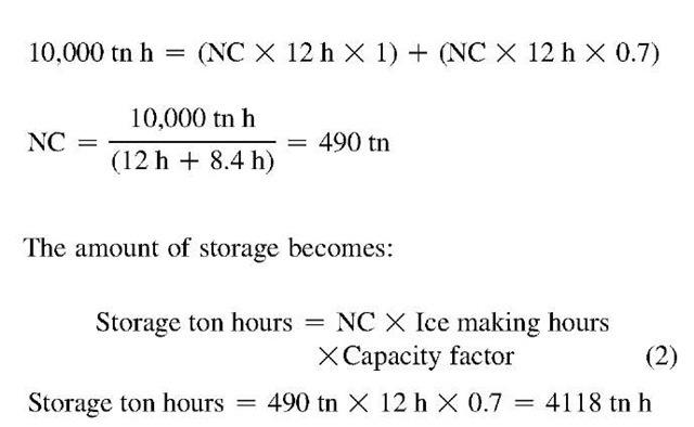
In this simplest of cases, the day capacity is zero, because the chiller is off. The ice-making capacity, at this point unknown, will be less than the chiller’s nominal daytime capacity. However, the relative daytime and ice-making capacities are easily determined for a particular chiller category. A centrifugal chiller, for instance, might produce 70% of its nominal capacity when in the ice-making mode, and 100% during the day. We usually want to describe the required chiller capacity in terms of its conventional rating and will therefore include a factor of 0.7 for hours operated at ice-making conditions. This is a capacity modifier, not an efficiency adjustment. Whether the efficiency is the same, better, or somewhat worse during charging will depend on a number of factors, such as nighttime condenser temperatures, arrangement and type of components, and choice of air or water cooled chiller.[13] With 12 h available for charging storage, Eq. 1 becomes:
where NC is the nominal chiller size. Of course, the required storage capacity is the entire 10,000 tn-h.
Another more common approach is to operate the chiller throughout the day, producing ice at night and directly contributing to the load during the day. At its limit, this results in the smallest possible chiller capacity, and equipment costs are often competitive with non-storage systems.
Fig. 6 Alternative TES selections for the same cooling load profile.
Note that this partial storage chiller is only 49% of the peak load and 41% of the full storage selection. Storage capacity is also reduced to 41% of the full storage requirement.
There is any number of intermediate selections. For instance, a common conventional design might include three 400-tn chillers for our 1000-tn building. An alternative is to select two 400-tn chillers and storage equal to the ice-making capacity of one of the machines, or about 3360 tn-h for our example. Similar redundancy is provided in the event of a chiller failure, with the added benefit of permanent operating cost savings.
Other multiple chiller options are possible. Certain utilities experience high, but relatively short, afternoon demand peaks, and a common alternative in these areas treats a 4-6 h period of the day as full storage. Other applications, churches for instance, may operate on multiple-day cycles, or industrial applications may experience a series of brief but intense cooling loads over the period of several hours. Fig. 6 depicts some possible selections and the on-peak chiller reductions that are possible with the more common daily cycles.
System Layout and Control
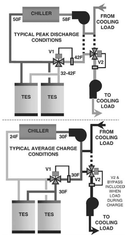
The final step is to construct a simple schematic representation of the proposed system and verify the control logic. A common partial storage design places the storage and chiller in series (Fig. 7). Our example positions the chiller upstream of the storage relative to the cooling load, but the reverse is sometimes preferred. Remember that in the internal melt system, the only fluid circulating is the freeze-protected coolant; the storage water/ice never leaves the storage tanks.
Note the modulating three-way valve located at the storage system. This valve automatically controls coolant flow through the storage tanks to maintain the desired coolant temperature throughout the discharge period as ice is melted.
Fig. 7 Ice storage system schematic—charge and discharge.
During charging, the chiller operates at the lower ice-making temperatures. The three-way valve directs all flow through storage. With no direct cooling needed during the ice-making period, the load can simply be bypassed. If there is a cooling load during ice-making, a second three-way valve and bypass is sometimes included (dashed lines) so that warm coolant returning from the load can be blended with the cold ice-making coolant before being sent to the cooling coils. The ability to efficiently meet small nighttime loads is often seen as a major storage advantage. A separate chiller often serves substantial nighttime load.
Discharge logic is dependent on the utility rate, equipment limitations, cooling loads, and the level of on-site supervision. The chiller can simply be set to provide the design supply temperature (e.g., 42°F [5.6°C]). Storage will only be discharged if the smaller chiller cannot meet the load. The amount of ice melted each day is minimized, referred to as chiller priority. Alternately, on cooler than design days, the chiller leaving temperature can be raised to increase the load on storage (storage priority) and take advantage of additional demand or energy cost savings.
Of course, the danger is that an error in the estimated total cooling load may exhaust storage, leaving only an undersized chiller to carry the load later in the day. Even unsophisticated systems, however, successfully employ this strategy by incorporating adequate margins in the level of chiller loading.[14]
Verify Initial Assumptions
Once the control and operating sequences have been established, return to the original selection calculations to insure that chiller and/or storage contribution, device operating temperatures, and modes of operation remain consistent with original assumptions. There are many alternative designs. Some include parallel flow arrangements, additional heat exchangers, or chillers. By applying the proposed logic on an hour-by-hour basis, the designer is assured of reliable performance.
BRIEF REVIEW OF OTHER TES OPTIONS
There are, of course, many other interesting and promising areas of TES technology. In some cases, precooling of the building structure and contents provides significant storage.[5] Research in this area is identifying and quantifying relevant design parameters, such as the location and type of auxiliary mass, effects of space dimensions, control methods, and potential benefits.
Underground thermal storage systems are used for both cooling and heating. Ground water from aquifers (ATES) is transferred between a warm well and cold well, extracting or adding heat either directly or through a heat pump. Alternatively, a closed loop array of vertical heat exchangers is placed into boreholes (DTES). Some issues that influence the choice or design of these systems include the balance between seasonal heating and cooling loads of the building, local geology, topography, hydrology, extraction and reinjection flow rates, and impact on neighboring water use (wells).[15]
Some winter-peaking utilities promote off-peak heat storage. A common design distributes an array of electric resistance heaters throughout a matrix of high-temperature ceramic (or other refractory) bricks within an insulated cabinet. Temperatures in excess of 1400°F (760°C) can be reached, providing large storage capacities in a small volume utilizing only sensible heat effects. A fan circulating air through passages within the storage device may assist discharge.[16]
Heat storage, combined with passive solar techniques, can be very effective if properly applied with regard to local climate, space geometry, etc. The Trombe wall, popularized in the mid-1960s, provides insight into several solarheating principles,1-4-1 and, of course, the simple hot water tank is a common storage vessel for active solar systems.
CONCLUSION
Progress continues in many areas of TES. Unique applications, like combustion turbine inlet air-cooling that recovers capacity normally lost during hot weather, are continually being developed.[17] Efforts are currently underway to describe more precisely TES performance in energy modeling software, motivated largely by increasing interest in the U.S. Green Building Council (USGBC) LEED®[18] certification program. Thermal storage is a uniquely diverse area of energy technology with both a long history of reliable use and the emerging potential of new and interesting developments.
