Abstract
This article reviews the history of steam turbine development for power generation and marine propulsion. It describes factors affecting thermodynamic and fluid dynamic efficiency and mechanical design principles. Alternative design technologies are described and some comparisons are given. Steam turbines for various applications and probable future developments are described.
INTRODUCTION
The steam turbine has been the predominant prime mover for electricity generation for a century. Its efficiency depends on steam conditions, steam cycle, and turbine fluid dynamic efficiency. Materials properties and mechanical design determine possible steam conditions and turbine rating. Fluid dynamic efficiency is determined by blade and steam path design. These factors and their interaction are described. The changing role of the steam turbine to combined cycle applications, with uncertainty regarding the scope for fossil-fired applications using advanced steam conditions and for new nuclear power plants, is discussed.
HISTORY
Hero of Alexandria’s “aoelipile” demonstrated steam-driven rotary motion in 200 B.C. It was driven by the thrust of two tangential outlet pipes and was therefore a reaction turbine. In Italy in 1629, Branca proposed fixed steam jets impinging on rotating blades—the impulse turbine. Both machines were without practical application. Until 1900, motive power was dominated by steam engines. In 1784, James Watt dismissed the turbine as a competitor. He reasoned that steam at boiler pressure would escape to the atmosphere at 2000 ft/s; and because blade speeds of half that were required to extract a useful proportion of its energy, it was impossible to construct a machine to withstand the resultant centrifugal loading. In 1837 in the United States, William Avery used Hero’s concept to build machines up to 5 ft in diameter, with peripheral speeds of 900 ft/s, to drive woodworking machinery. They were abandoned because of control difficulties and unreliability. Gustav de Laval in Sweden used a similar device to power a centrifuge, then in the 1890s turned to single-stage impulse turbines. These used a convergent-divergent nozzle to fully expand the steam and had rotor speeds of up to 30,000 rpm. The ascendancy of the steam turbine began when Charles Parsons solved the problem of high velocities by applying pressure compounding to divide pressure drop between a large number of reaction stages along the axis of the turbine. In a year from 1884, he patented and demonstrated the first practical turbine generator. In 1886 in France, Professor Rateau pressure compounded the impulse turbine. In the United States, electrification proceeded rapidly, and in the mid-1990s, George Westinghouse acquired U.S. rights to Parsons’ patent and installed the first commercial turbines in 1899. Charles Gordon Curtis addressed the steam velocity problem by velocity compounding; i.e., directing steam from a single row of nozzles onto several rows of moving impulse blades with intervening fixed guide blades. Vertical-axis 5-MW Curtis Turbine Generators were installed in Chicago in 1903. In the United Kingdom, the most rapid development was marine. In 1897, Parsons raced through a fleet review by Queen Victoria in his launch, Turbinia. It was capable of 34 knots, and outpaced the fastest Royal Navy patrol boats. The implications were clear, and by 1905, turbine power was exclusively selected for British warships. It was also used for liners from 1906 until the end of their era.
After 1910, development was rapid, aided by the acceptance of alternating current, which permitted efficient blade design in turbines direct coupled to generators operating at 3600 rpm (60 Hz) in the United States and 3000 rpm (50 Hz) elsewhere. By the 1920s, efficiency was improved by condensers, superheating, and feed heating. In marine applications, multiple reduction gearing allowed diameter and speed to be optimized, resulting in major increases in efficiency. Impulse turbines had the advantages of high power density, smaller rotors, and greater tolerance of rapid temperature changes. They were affected by blade vibration but came to dominate this field after World War II. Reheat was adopted generally at this time, and turbine generator size and efficiency continued to increase. Supercritical steam cycles with steam pressure and temperature conditions of 340 bars/650°C and double reheat were introduced in the 1960s. Materials difficulties caused reduction to 240 bars/560°C, typical of supercritical units now in service in the United States. Steam turbines operating at up to 250 bars/600°C are used in Europe and Japan. Nuclear reactors require low-speed, wet-steam turbines of up to 1500 MW operating at 75 bars/295°C. In the last decade, combined cycles have become a major steam turbine application. In the marine field, the liners were eliminated by airlines soon after World War II. Rising fuel costs and large, very efficient diesel engines eliminated steam turbines from merchant ships by 1980, despite attempts to compete using very advanced 210 bars/600°C, 14,000-rpm designs. Naval propulsion is now predominantly gas turbine and diesel except for nuclear powered capital ships and submarines.
STEAM CYCLES
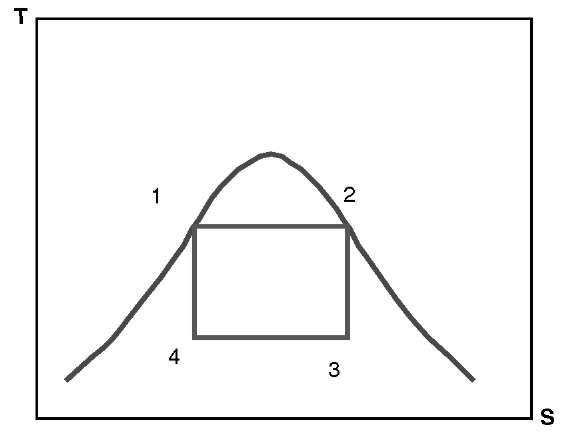
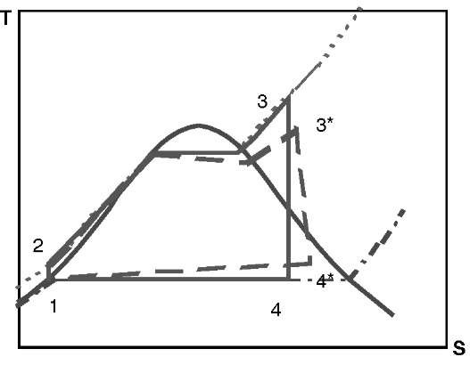
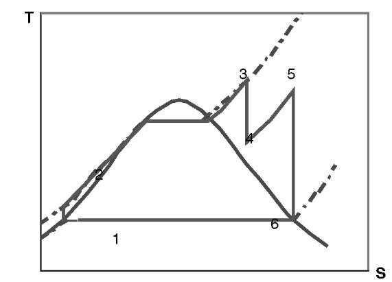
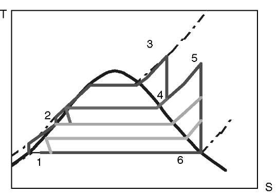
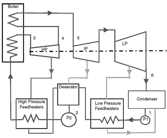
The Carnot cycle, shown in Fig. 1, is the most efficient fluid power cycle. It illustrates principles and the reasons for more complex cycles. Processes are as follows: 1-2, reversible isothermal heating in the boiler; 2-3, isentropic expansion in the turbine, 3-4, reversible isothermal condensation; and 4-1, isentropic compression. The area under 1-2 represents heat from the boiler, and that under 3-4 represents heat rejected to the condenser. The difference between the two areas is the work produced. Carnot Efficiency is defined as (Tmax— 7mjn)/rmax. In a steam cycle, the condenser cooling medium fixes Tmin; and increasing Tmax, the temperature at which heat is supplied, maximizes efficiency. This cycle is impractical because isothermal heat supply is only possible in the two-phase region, limiting maximum cycle temperature to below the critical temperature of 374°C. Expansion of saturated steam gives poor steam quality at turbine exhaust, which would cause erosion of the turbine blades. A two-phase compressor is impractical. These difficulties are overcome by the Rankine cycle, shown in Fig. 2, in which heat is supplied at constant pressure from 2 to 3 in successive economizing, evaporating, and superheating. Superheating increases the average heat supply temperature and steam quality at turbine exhaust. Complete condensation from 4 to 1 necessitates only a liquid phase boiler feed pump. Fig. 2 also indicates the effect of irreversibility due to the fluid friction and heat loss in a real cycle. Fuel costs are many times capital costs; and therefore, a complex cycle is justified to maximize efficiency. The values of maximum cycle temperature permitted by creep properties of boiler and turbine materials result in considerable wetness after expansion. For a given maximum temperature, raising the pressure—hence, also raising boiling temperature and average heat supply temperature—increases efficiency. It has the disadvantage of increasing leakage losses and displacing the expansion line to the left, further increasing exhaust wetness. To reduce wetness, steam is returned to the boiler after partial expansion and reheated, as shown in Fig. 3. This further increases average heat supply temperature and efficiency by 4%-5%. Two stages of reheat are sometimes used in supercritical plants. In the economizer, heat is added at low temperature. Efficiency is therefore further improved in the Regenerative Rankine Cycle (Figs. 4 and 5) by feed heaters, heated by steam extracted from the turbine. Fig. 5 is simplified. In real plants, up to 10 feed heaters are used. The overall energy efficiency of the steam cycle is given by the heat rate, defined as the heat supplied by the boiler (in Btu) divided by the generator output (in MWhr).
Fig. 1 Carnot vapour cycle.
Fig. 2 Rankine cycle.
Fig. 3 Reheat rankine cycle.
Fig. 4 Regenerative reheat rankine cycle.
The use of a two-phase working fluid has major advantages. The efficiency of energy conversion in heat engines is a function of the pressure ratio. In petrol engines, this is about 12:1; in a diesel engine, 18:1; and in a typical gas turbine, 20:1. In the steam cycle, because of condensing, exhaust pressure is very low, and this ratio is at least 4000:1. The power required for the pump or compressor in the cycle is related to the change in volume. In the Rankine cycle, pumping takes place in the liquid phase; therefore, power requirements are 2 orders less than in a cycle using air as a working fluid. Energy release per unit mass of working fluid is very high, increasing the power density of the heat engine.
STEAM PATH
Steam is expanded in fixed blades or nozzles attached to the casing, and its enthalpy is converted to kinetic energy then to mechanical energy by moving blades attached to the rotor. In the United States, blades are referred to as buckets. The efficiency of the conversion is the ratio of the actual turbine work in process 3* to 4* (Fig. 2) to the isentropic turbine work in process 3-4. This ratio depends on turbine design and losses but is greater than 90% in modern machines. A row of fixed blades and the following row of moving blades is called a stage. The combination of rotors and casings between bearings is a cylinder. This may include two flow paths. Specific volume, and therefore required steam path flow area, increases by a factor of 2000 from inlet to exhaust for subcritical turbines, and by a factor of 3000 for supercritical turbines. This is accommodated by increasing the blade height and rotor diameter from stage to stage through the steam path from the inlet through high- (HP), intermediate- (IP), and low-pressure (LP) cylinders; and, if necessary, by double-flow IP and several double-flow LP cylinders.
Blades and Seals
In a pure impulse stage, pressure drop occurs across the fixed blades and enthalpy is converted to kinetic energy.
Fig. 5 The regenerative reheat rankine cycle.
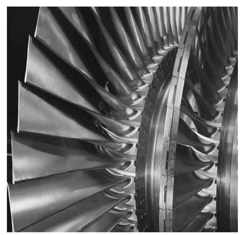
Moving blades change the direction of the steam so that energy is transferred to the rotor entirely by change of momentum. Only Hero’s concept is pure reaction. All blades have an impulse component. In reaction stages, the flow path between rotating blades is shaped to cause further pressure drop, expansion, and kinetic energy release, which is transferred to the rotor by reaction. The percentage of enthalpy drop across the moving blades is the degree of reaction. Also, in any blade, centrifugal effects in the space between fixed and moving blades increase pressure drop across the latter, and therefore the degree of reaction with radius. All blades have some degree of reaction, varying from a minimum of 5% in “impulse” to 50% in “reaction” designs. These differences have a marked effect on HP and IP design. In impulse design, stationary blades are arranged in rigid diaphragms with a labyrinth seal to the rotor. The diameter of the seal, and therefore leakage area, is minimized. Between seals, the rotor diameter is increased to form a wheel to which the rotating blades are attached. This construction is called “diaphragm and wheel.” The pressure drop across moving blades is small, but sufficient to require a tip seal. In reaction design, it is greater and requires higher tip seal duty per moving blade row. It also causes an axial thrust on the rotor; therefore, annular area between the fixed and rotating blade seals must be a minimum, precluding diaphragm and wheel construction. Rotors of cylindrical or slightly tapering conical form, referred to as drum rotors, are used. Thrust is balanced either by a large annular rotor surface subject to steam pressure, a dummy piston; or by combining opposed flows in the same cylinder. For the same enthalpy drop, a reaction turbine requires about twice as many stages as an impulse turbine, but the two concepts have remained competitive through their development histories to present, both having very high efficiencies. Reaction stage efficiencies are higher, but differences in overall turbine efficiency are evidently small, and could only be identified from proprietary information. Diaphragm and wheel construction has the advantages of compactness and lower transient thermal stresses. In LP blades, differences between the two concepts diminish. The last stage can produce up to 10% of total turbine output and is most important in turbine efficiency. Steam volume is large and blades are up to 1.2 M long in 3000 rpm machines. There is a large change in blade speed from root to tip, whilst the axial steam flow is more nearly constant. To align with the resultant steam flow, the angle of the blade is twisted from near axial at the root to near tangential at the tip. Increases in the degree of reaction from root to tip due to centrifugal effects are large, and a marked change in blade profile is required. Blades with these features are known as vortex blades. Full analysis of LP blades is complex and has only become possible in the last two decades with the advent of computational fluid dynamics, correlated with experiments. Their optimization is one of the major recent advances in turbine design.
Losses
Turbine efficiency is determined by fluid dynamic, leakage, wetness, and leaving losses. Fluid dynamic losses due to surface friction and secondary flows are small in modern HP but more significant in impulse stages and LP blades, due to higher steam velocities. Curved nozzles, which lean in the tangential direction, have been developed to reduce secondary flows. Leakage losses due to steam bypassing the tips of moving and stationary blades are more significant in HP, particularly in reaction stages. In LP stages, when steam is wet, water droplet velocities are less than steam velocities and cause drag on, and erosion of, moving blades. Stage efficiency reduces by approximately 1% for 1% additional wetness. Within the steam path, kinetic energy leaving one stage is used in the next, but that leaving the last stage is lost in the condenser. “Leaving loss” is proportional to the square of exhaust velocity. The greater the diameter of the last stage blades and the number of exhaust flows (and therefore the greater the exhaust area), the lower the leaving loss. This is one of the most important issues in determining turbine size, cost, and efficiency. The design of the duct between the turbine exhaust and the condenser—the exhaust hood—is also important. Modern designs can produce a backpressure below condenser pressure, so increasing turbine output.
MECHANICAL DESIGN
Turbines must be designed for temperatures of up to 600°C; pressures of up to 300 bars; transient thermal stresses (mainly during startup and shutdown); and fluid dynamically, and mechanically induced vibration, corrosion, and erosion. In HP cylinders, centrifugal loading essentially depends on peripheral velocity, which is defined by blade efficiency. Optimum designs for pressure containment and minimum thermal stresses are obtained by minimizing rotor diameter and casing thickness, and therefore by achieving high rotational speed. For power generation, gearing is impractical; therefore, optimum rotational speed is either 3000 or 3600 rpm, depending on grid frequency. Impulse designs have advantages with regard to thermal stresses. They have a smaller rotor body, which reduces maximum values, which also do not occur at stress concentrations due to blade attachment details. For LP rotors with large blades, centrifugal loading depends on speed of rotation; therefore, 1500 or 1800 rpm allows the largest blades and exhaust area. For these reasons, until about 1970, large turbines were optimized by cross compounding with a high-speed HP/ IP shaft and a low-speed LP shaft, requiring two generators and very large turbine halls. Developments in LP blade design now enable much more compact machines of over 800 MW to be built with 2 LP cylinders, and up to 1100 MW with 3 LP cylinders, both using a single high-speed shaft.
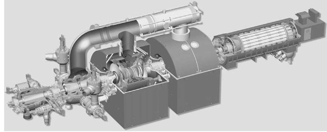
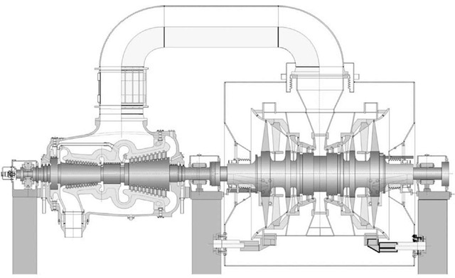
Fig. 6 Arrangement of 4 cylinder up to 1200 MW, 300 bar, 600°C, reheat steam turbine.
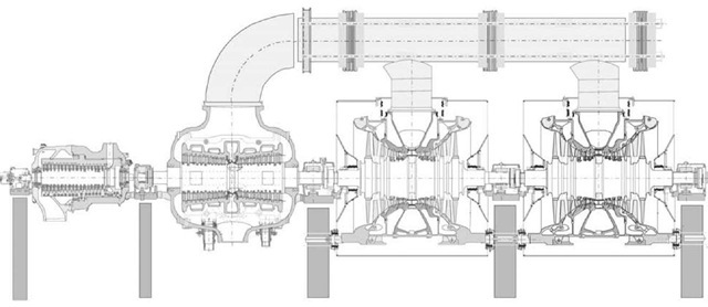
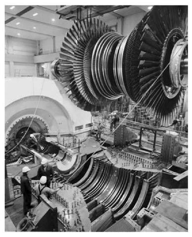
Creep properties of high-temperature sections, tensile strength of LP blades and rotors, and toughness to prevent failure of rotating components are the most important material issues. Turbines are large capital investments and must operate reliably for more than 30 years—200,000 h with minimum possible outages. In the past, design was evolutionary; but modern practice is increasingly influenced by engineering analysis of thermal, mechanical, and chemical operating and fault conditions; and by materials development. Extremely high reliability has been achieved. Overhaul intervals approaching 10 years are possible, justified by condition monitoring, and machines’ lives extended to more than 40 years. Figs. 6 and 7 show a large modern reaction turbine with a single-flow HP cylinder, a double-flow IP, and two double-flow LP cylinders. Condensers are beneath the LP cylinders. This configuration is used for ratings to over 800 MW and supercritical steam conditions approaching 600°C and 300 bars with a single reheat. Rigid couplings connect all rotors, including the generator. One LP casing is anchored to the foundations to minimize expansion movement relative to the condensers. Other casings are supported on sliding feet to allow free longitudinal expansion. A single thrust bearing is positioned to minimize axial differential expansion between the rotors and casings. Bearings are set at different levels, matching the deflected forms of the rotors to minimize rotating bending stresses. High pressure and IP cylinders have inner and outer casings. The inner casing, which carries the stationary blades, contains the difference between the stage pressure and the cylinder outlet pressure. The outer casing contains the outlet pressure. This allows the casings to be thinner, minimizing thermal stresses. In other designs, pressure loading on the casing is further reduced by use of an impulse first stage and a separate inlet nozzle box containing the large pressure drop across the first-stage nozzle. This also reduces the number of stages at some cost in efficiency. Most turbines have horizontal bolted joints in both inner and outer casings to permit assembly and maintenance. Massive flanges with a very high ratio of bolt to flange area are required. Because the casing heats up more rapidly than the flanges during start up, rates must be limited to minimize thermal stress, distortion, and thermal fatigue. In impulse designs, diaphragms reduce leakage caused by casing distortion. In some designs, inner casing bolts are replaced by shrunk-on rings requiring complex assembly and disassembly. High pressure and IP Casings are steel castings; generally, 1%-2% chromium alloys for sub-critical turbines and 9%-12% Cr for supercritical turbines. Low-pressure casings have an inner nodular cast-iron casting carrying the blades, supported in a fabricated steel outer casing including the exhaust hoods. Fig. 8 shows assembly of an LP cylinder. High pressure and IP rotors are one-piece forgings in similar materials to those of the casings, alloyed to maximize toughness. Low-pressure rotors for fossil-fired applications are also normally one-piece forgings. Those for wet steam nuclear turbines comprise a shaft with shrunk-on disks to carry the blades. Compressive stresses in this design increase its resistance to stress corrosion cracking. Because of the high centrifugal loading due to very long blades, low-nickel, chrome, vanadium alloys with very high strength and toughness are used.
Fig. 7 Section of 4 cylinder up to 1200 MW, 300 bar 600°C, reheat steam turbine.
Fig. 8 Low pressure cylinder assembly.
Blades are generally 12% chromium or higher steel alloy forgings. They are attached to the rotor by a mechanical connection consisting of a lobed male detail on the blade and an identical female detail on the rotor. The design most commonly used for LP blades is shown in Fig. 9. Similar concepts oriented circumferentially are used for attachment to drum rotors. Multiple pinning through a forked blade root and the disk, over which it is fitted, is also used. Mechanical design of last-stage blades is one of the major factors controlling turbine output and configuration. Length is determined by centrifugal loading. Titanium is now used to increase the material-strength-to-weight ratio. Blade vibration and avoidance of high-cycle fatigue are also major considerations. In the past, blades were rigidly connected in groups to control vibration. Two design approaches are now in use. The blade on the left of Fig. 9 is free standing, designed to ensure that no modes of vibration are excited in operation. The alternative is continuous circumferential connection, suppressing some modes and providing damping. Fatigue of inlet HP blades is also important when steam is admitted over only part of the circumference, and steam forces on the blade vary as it enters and leaves the admission zone.
Sealing is by “labyrinth packings.” These consist of several thin metal disks, spaced axially and mounted on the casing with minimum clearances from the shaft. Resistance to leakage is provided by the small clearance gaps in series, and by creating a tortuous flow path. Materials are chosen to prevent damage to the shaft, should a rub occur. Glands, seals between casings and rotors, are required to prevent outward steam leakage from HP and IP cylinders and inward air leakage to LP cylinders, which would reduce condenser vacuum. These consist of several labyrinth packings in series. Steam at IP is introduced between two packings. This controls the pressure gradient along the seal, minimizing leakage. Leakage increases the heat rate, and is minimized by intermediate leak-off paths routed to the feed system. Steam which passes through the whole assembly is captured by a gland steam condenser, maintained at subatmospheric pressure.
Fig. 9 Low pressure rotor.
Hydrodynamic white metal journal bearings are used. For LP cylinders, bearings with length greater than diameter are required to obtain suitable bearing pressures. When the turbine is shut down, HP and IP rotors remain at temperatures at which permanent creep bending under self-weight would occur. To prevent this, it is essential to rotate the turbine slowly until it cools sufficiently. This is referred to as “barring.” Under these conditions, the hydrodynamic oil film is not developed, and alternative pressure lubrication is normally provided.
TURBINE CONTROL
Valves in the steam chests, which can be seen in Figs. 6 and 11, control speed and load. If these are operated in parallel, the turbine is “throttle governed,” and steam flow and pressures through the turbine are proportional to load. The disadvantage is that there is a loss of efficiency at part load due to throttling in the valve. Operating the valves sequentially can reduce this. At part-load, when only one valve is used, throttling is less. This is “nozzle governing.” Throttling losses can also reduced by operating the boiler at variable pressure; i.e., sliding pressure control, used in combined cycle steam turbines. “Bypass governing,” whereby steam is admitted partway down the steam path, can be used if the boiler must operate at constant pressure. Overspeed in the event of load loss and consequent damage is prevented by rapid closure of the valves. In this situation, energy stored in steam in the reheater and feed systems must be isolated from the turbine by further rapidly acting valves.
TURBINE TYPES
The machine shown in Figs. 6 and 7 is typical of those used in a modern fossil-fired plant. The predominant fuel is coal, but lifetime fuel costs are still several times capital cost; therefore, a supercritical plant is generally built. The most common size is about 600 MW, but up to 1200 MW is possible with two LP cylinders. For smaller sizes, the configuration shown in Fig. 10 is attractive and widely used. It is suitable for loadings up to 500 MW, with subcritical steam conditions of 177 bars and up to 600°C. The cylinder on the left includes opposed-flow HP and IP turbines. Steam enters near the center, expands to the left in the HP, is reheated to approximately the same temperature, re-enters near the center, expands to the right in the IP, then exhausts to the LP via the outer casing. This configuration confines high temperatures to the center, reducing thermal stresses and allowing more rapid starting. It is more compact and economic than separate HP and IP cylinders.
Pressurised Water (PWR), Boiling Water (BWR), and Canadian deuterium uranium (CANDU) nuclear plants generate saturated steam at approximately 75 bars and 295°C. It is dried, admitted to the HP turbine, and expanded until it is about 10% wet. It is then exhausted to water separators and superheated in a steam-to-steam heat exchanger before admission to the LP turbine. Low-pressure superheating increases average heat supply temperature and efficiency and limits wetness to about 10% at exhaust to the condenser. Such steam turbines drive four-pole generators and rotate at half the speed of conventional machines. For a given output, flow areas are doubled and velocities are halved. This results in very large, multicylinder turbines but has the advantage of reducing blade erosion by water droplets in wet steam and reducing leaving loss. Machines of up to 1500 MW with three opposed-flow LPs have been built.
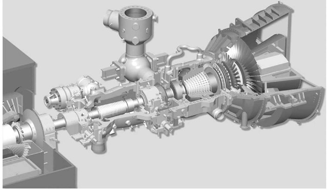
Because of lower heat rates, capital costs, and construction times than conventional steam plant, combined cycle gas turbine (CCGT) is now the largest application of steam turbines. Gas turbines exhaust into individual heat recovery steam generators (HRSG’s). One or more supply steam to the steam turbine. If only one is used, the gas and steam turbines are arranged on a common shaft, connected by a clutch to allow the gas turbine to be started first. To obtain maximum heat recovery, up to three steam pressures are used in the HRSG, and steam is admitted to the turbine at three positions along the steam path, increasing steam flow from inlet to exhaust. No feed heaters are used, and steam extraction is only for the deaerator. The importance of last-stage blade efficiency is increased. Fig. 11 shows a typical two-cylinder machine for combined cycle application. It is capable of up to 250 MW, with steam conditions of up to 600°C and 170 bars. It is designed for installation on a flat foundation with an end-mounted condenser.
Steam turbine generators are frequently combined with process plants. This is called cogeneration. If the process requirements and generation requirements are fixed, steam is produced at a higher pressure and expanded in a back pressure turbine driving a generator, then exhausted at the pressure required for the process plant. If the steam required for the process is less than that for generation, a pass-out or extraction turbine is used, process steam is extracted from the turbine after partial expansion, and the remainder fully expanded before exhaust to the condenser.
Fig. 10 Arrangement of 2 cylinder up to 500 MW, 177 bar, 600°C, reheat steam turbine.
DEVELOPMENT
Steam turbine technology is thoroughly evolved, and the limits set by material properties and fluid dynamic efficiency are well defined. Applications depend on other technologies. Combined cycles require relatively simple machines with emphasis on maximum exhaust efficiency. Developments will probably be the more complex steam path requirements of advanced gas turbines using steam-cooled gas turbine blades and integrated gasifiers. Coal remains a major energy source, and the supercritical steam plant with exhaust conditioning is an economically and environmentally competitive technology for burning it. Related developments are supercritical steam turbines for steam conditions above 700°C, longer last-stage blades, and units with larger outputs and fewer cylinders. Steam turbines are essential for power production from water-cooled nuclear reactors, and steam conditions may increase and unit ratings may reduce in the future.
Fig. 11 Arrangement of 2 cylinder up to 250 MW, 177 bar, 600°C, reheat steam turbine, suitable for combined cycle applications.
CONCLUSION
The steam turbine is an elegant concept, capable of converting the energy of steam into mechanical work solely by rotary motion. Condensation of steam enables exceptionally high pressure ratios and energy extraction. Its characteristics as a prime mover are ideal for electricity generation. A steam power plant is capable of over 40% overall energy efficiency, firing a wide range of fuels. The turbine’s mechanical elegance results in low maintenance requirements and long service life. For these reasons, it has remained predominant in this application for a century. In this period, efficiency and power density have increased by factors of more than 4, and remarkably, two alternative steam turbine technologies have developed competitively throughout. It had a major role and underwent major development in marine propulsion. This ended because of changes in shipping economics and large, highly efficient diesel engines. Sole predominance in power generation is now ended by large gas turbines, but only combination with the exceptional energy recovery of the steam tubine enables efficiency over 55% to be achieved in combined cycles. These can be adapted to all fuels by the use of gasifiers. Applications of large turbines for nuclear reactor power cycles and coal-fired steam plants with potential for power outputs of up to 1700 MW will continue; but their relative importance depends on a resurgence of nuclear power in response to global warming, the availability of gas to fire CCGT, and advanced clean coal technologies, including gasifiers.
