Abstract
Mechanical cooling is one of the largest end uses of electricity, and it contributes significantly to peak demand and on-peak energy consumption. The ability to offset electricity consumption during peak usage periods by eliminating mechanical cooling can save costs, reduce strains on transmission grids, and free up much-needed peak period capacity for electric generation utilities. Solar energy use, long encouraged for offsetting space heating and daylighting energy consumption, can now be utilized for offsetting cooling consumption. By using solar heat to regenerate a desiccant dehumidification system, and utilizing direct and indirect evaporative cooling to condition superheated dry supply air, occupied spaces can be cooled using no grid energy input. A demonstration project has been designed to cool an inspection station at the U.S. Pentagon in Arlington, Virginia, and is expected to provide 65°F, moderate humidity air at summer design conditions.
INTRODUCTION
An inspection station at the Pentagon Central Plant currently uses a through-wall heat pump for cooling and heating. This station was chosen for a demonstration project to test the application of space cooling using only solar thermal, desiccant dehumidification, and indirect evaporative cooling. By using collected rainwater for evaporative cooling and photovoltaic panels with battery back-up to run peripheral equipment, this system will have the potential to operate completely off grid, with no purchased electricity or associated emissions. Cool air will be provided directly to the station using a four-stage process:
Stage 1 : An American Solar Inc. tile roofing system will be used to heat ambient air up to 200°F.
Stage 2 : Supply air for the station will be dehumidified and superheated using a small desiccant wheel. The wheel will be regenerated using the solar heated air.
Stage 3 : The superheated air will be cooled using a direct air-air heat exchanger with ambient air.
Stage 4 : The hot air will be further cooled using two stages of indirect evaporative cooling, first with saturated ambient air and second with aportion of the supply air diverted into a second indirect evaporative cooler.
Based on a psychrometric analysis, it can be shown that 65°F 60% relative humidity (RH) air can be delivered from Washington, DC, design ambient conditions of 85°F dry bulb (DB)/75°F wet bulb (WB).
COOLING SYSTEM METHODOLOGY
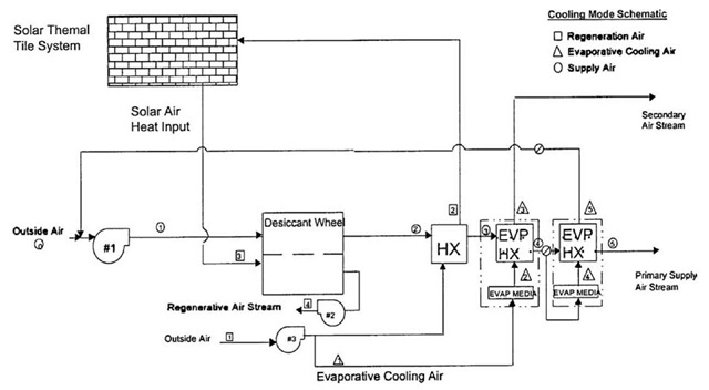
The cooling process designed utilizes three separate air streams: the supply or primary air stream, the secondary air stream, and the regenerative air stream (RAS). Further details of each of the equipment used will follow later in this abstract. Fig. 1 is a schematic of the design.
The primary air stream is drawn from outside air through air filters and is mixed with the exhaust air from the second evaporative cooler (IEVAP-2). This mixing process reduces the enthalpy and temperature of the incoming air during design conditions. The primary air then passes through the dehumidification side of the desiccant wheel (DESC-1). The air is then passed through an air-to-air heat exchanger (HX-1) with the regenerative air to cool the primary air. In the next stage, the primary air is further cooled by passing through an indirect evaporative cooler (IEVAP-1). Finally, the primary air passes through a Maisotsenko-type indirect evaporative cooler (IEVAP-2) to provide the final conditioning for the supply air. During this final stage, the primary air is divided into the primary air stream and an exhausted secondary air stream.
Fig. 1 System schematic.
The secondary air stream feeds IEVAP-1. The secondary air stream is intended to maximize the removal of sensible heat from the primary air and thereby reduce the primary air temperature. To this end, the airstream is designed with twice the airflow as the primary air.
Similar to the primary air stream, the RAS is drawn through air filters from outside. This airstream is first passed through HX-1 to recover heat from the superheated and dried primary air stream. This preheated air is then sent to the solar roof tile system to capture the solar energy and raise the RAS temperature. The solar heated regeneration air passes through the regeneration side of the DESC-1 to enable the desiccant to release and exhaust the absorbed moisture into the air stream.
PSYCHROMETRIC ANALYSIS
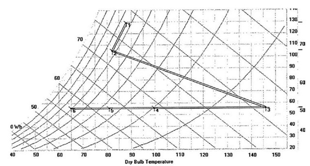
Fig. 2 illustrates the psychrometric path of the primary air stream. It begins at State 1—a high temperature, high humidity, and high enthalpy condition. The exhaust from the IEVAP-2 is saturated with water vapor, but has a lower temperature-humidity ratio and enthalpy than the outside air. The mixing of the airstreams reduces the overall enthalpy at State 2. State 3 occurs after the desiccant wheel; as expected, the moisture content is greatly reduced while the temperature is significantly increased. It is important to note that the total enthalpy of the air is actually increased from State 2 to State 3. States 4-6 are the result of sensible-only cooling through the heat exchange with other air streams in HX-1, IEVAP-1, and IEVAP-2. The overall result is a strategy that first shifts the enthalpy of the airstream from latent to sensible energy, and then uses heat exchange with original or tempered outside air to remove the sensible energy and produce cool air without the mechanical cooling.
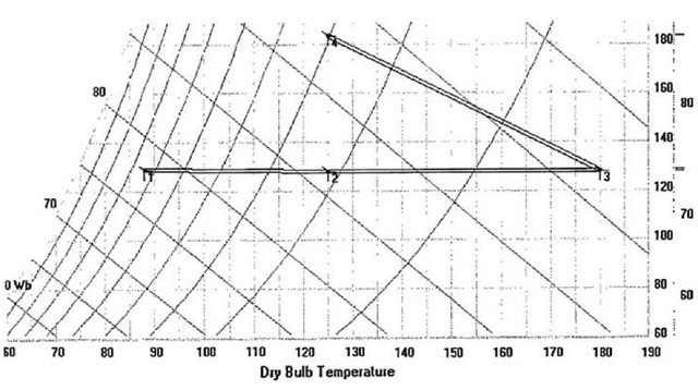
As Fig. 3 shows, the psychrometric path for the RAS is simple. It starts at State 1, the outside air conditions, and gains sensible heat from the heat exchange at HX-1 to arrive at State 2. The air stream is further heated sensibly by the solar irradiance captured from the solar tile system, and reaches the regeneration temperature at State 3. Once the RAS has passed through the desiccant wheel, State 4 represents the cooler, wetter exhaust air containing the additional moisture from the desiccant.
SOLAR ROOF TILE SYSTEM
American Solar, Inc. has patented a technology to provide solar-heated air using a tile roof system. The solar thermal tile system is designed to provide dual functionality: to serve as the roof of a space and to provide solar heated air. This system translates a portion (~ 35%) of the solar insulation available in a given region into preheated air, which can be utilized for heat exchange, thermal storage, space heating, and in this case, desiccant regeneration air. Radiant energy is absorbed by black-painted metal absorbers and heats the air surrounding the absorbers. Transparent tiles over the absorbers contain the heated air, and allow a fan system, at a plenum at one end of the roof, to collect the solar-heated air.
Stagnation tests show that a typical system can achieve internal air temperatures of > 200°F (94°C) and more than 130°F (72°C) above ambient temperature during the summer months. An air flow test with an early prototype showed outlet air temperatures of 160-180°F (71-82°C) are possible. Higher temperatures are expected with optimal orientation, improved materials (i.e., absorber, glass tile, etc.), and optimal air flow given a system’s configuration.
Fig. 2 Supply air stream psychro-metric path.
For this particular application, the preheated solar air generated from the solar roof will be used to regenerate a high temperature substrate desiccant, which will be utilized to dry the primary air stream. To achieve the temperatures need to regenerate this particular desiccant, the complete solar roof system had to be designed in three stages:
Stage 1 : This roof section includes about 150 ft2 of dark-colored standing seam panels, set at a tilt of 22.9° and facing north. The panels will heat up, and preheated air from underneath the seam panels will flow to the next roof section.
Stage 2 : This roof section includes about 150 ft2 of the ASI tile system, set at a tilt of 22.9° and facing south, that will boost up the temperature coming off the standing seam panels and deliver it to the next roof section.
Stage 3 : This roof section includes about 90 ft2 and faces south with an angled reflecting surface opposite it (to provide additional insulation). Stage 3 takes the incoming air from Stage 2 and increases the temperature of the air further. The air from Stage 3 is then delivered to the desiccant wheel for regeneration.
DESIGN AND CONSTRUCTION STRATEGY
The overall goal of this showcase project was to create an innovative and fully integrated cooling system which would also have the capability to provide solar-heated air for space heating in the winter. To provide power for peripheral equipment, such as fans and the water pump, several photovoltaic shingles will be installed in the roof system. This particular application will include battery a backup and backup grid connection for battery charging, but the showcase is meant to demonstrate the potential for off-grid applications. Highlighted design features and modifications for test bed purposes include:
• The ability to alter and test the impact of different face velocities across the solar roof to increase the regeneration air temperature.
• The ability to adjust the relief damper position for the regeneration air to properly pressurize the solar roof.
• The end user’s ability to adjust the temperature when the solar cooling system is not providing adequate supply air temperatures during muggy days or when there is little to no (night) solar isolation available.
Some of the challenges and system constraints include:
• The minimal amount of space available for routing ducts and mounting heating, ventilating and air conditioning (HVAC) equipment underneath the solar roof and above the 9′ carport ceiling limit.
• The integration of the solar system with the evaporative cooling system.
• The integration of the PV shingles and the ASI tile system into a single entity.
• Minimizing pressure losses through the supply system to minimize fan power consumption and energy losses
Fig. 3 Regeneration air stream psychrometric path.
CONCLUSION
There is a great potential to provide spot cooling for remote locations using solar-regenerative desiccant dehu-midification, heat exchange, and indirect evaporative cooling. The economics of such an installation will be greatly dependent on climate, energy rates, benefits of avoided grid extension, and other factors where adding mechanical cooling to a location is costly. The potential impact on operating costs, utility generation and transmission demand constraints, and environmental improvement from reduced emissions is significant.


