Abstract
The world has an abundant supply of natural gas, estimated at roughly 6000 TCF in areas with little or no local demand. This stranded resource has little value unless it can be delivered to areas of high demand that are willing to pay the price of production and delivery. This entry discusses the liquefied natural gas (LNG) export terminals, LNG ships, LNG receiving terminals, and pipelines that make up the chain that can provide a bridge for local communities and industry to access the vast natural gas resources around the world.
INTRODUCTION What is LNG?
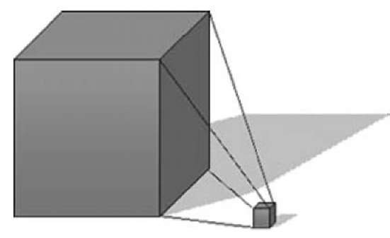
Liquefied Natural Gas is natural gas that has been supercooled to — 259°F and changed from a vapor to a liquid. Liquefaction reduces volume by 600 to 1 (Fig. 1). Stored cold in insulated containers at near atmospheric pressure, LNG is colorless, odorless, noncorrosive, and nontoxic. Liquefied Natural Gas becomes lighter than air when vaporized.
HISTORY
Serving as a foundation for this rapidly growing industry is cryogenic technology, which has long-established roots from man’s interest in the cold and the supercold. Man’s desire to produce ice from water at will apparently is extremely old. The cooling effects of evaporating water, to the point at which ice forms, were known to the ancients of Egypt and India.
During the mid-18th century, scientists were at work in the laboratory on two fronts. Those of an experimental persuasion were engaged in constructing machinery in an effort to produce cold, while those of a more scientific bent were engrossed in trying to derive the gas laws, determine material properties, and unravel the mysteries of work and heat.
Cryogenic technology, thus begun, advanced rapidly under the impetus of two sources: (1) laboratories employing low temperatures for basic studies in chemistry and physics, and (2) suppliers of liquefied gases for
industry. The contribution of the suppliers has been the development of new cryogenic processes for separation and purification of gases, and more efficient methods for gas liquefaction. Research laboratories, on the other hand, have been more concerned with the methods of producing the low temperatures needed in their experiments.
LIQUEFACTION
A natural gas liquefaction plant converts the gas received from pipeline or distribution mains into a liquid suitable for transport or storage. The plant consists of two main sections:
1. Feed preparation or pretreatment section—for the removal of carbon dioxide (CO2), water, and other natural gas constituents that could form solids when the gas is refrigerated and affect the liquefaction process, or adversely affect the quality of the revaporized LNG.
2. Liquefaction section—for the removal of sensible and latent heat from the gas to convert it to a liquid at atmospheric pressure.
Liquefaction of natural gas requires basically the removal of energy in the form of sensible and latent heat. There are several processes available and various modifications of each process that will accomplish this heat removal. The selection of the best process for a particular plant can be made only after a thorough study of the local conditions. In some cases several different processes may fit a particular application.
There are two basic means of accomplishing this heat removal:
1. By transfer through refrigerants to a high-level heat sink, such as cooling water or air. This method uses one of the following: (a) a cascade cycle using several single-component refrigerants or (b) a modified cascade cycle that circulates a blend of refrigerants in a single refrigerant circuit. Both types use rotating compressors with large fuel gas consumption. The cost of constructing these facilities and operating efficiencies typically determine which process is selected for a given location. Fuel gas can be as high as 8%-12% of the total throughput.
Fig. 1 600-to-1 volume reduction.
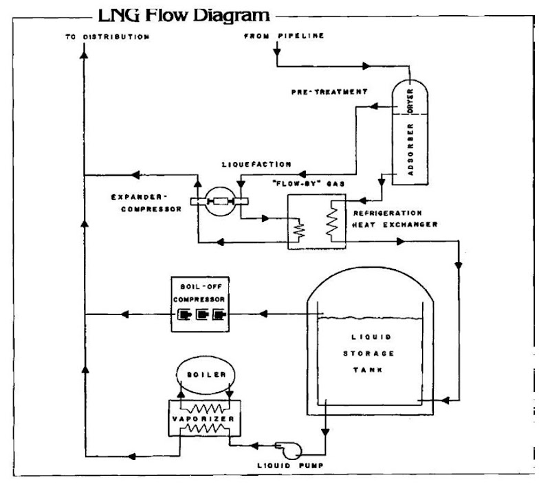
2. By permitting the gas to do work through the use of an expander (Fig. 2). The expander cycle can utilize the pipeline pressure and expand natural gas, or it can use a compressor-expander combination using a separate gas (i.e., nitrogen) as a circulating refrigerant. The expander typically uses less fuel gas when a letdown pressure is used as the energy source. In the past few years, both types of plants have been built and are in operation.
STORAGE
Large volumes of natural gas can be stored in the liquid state because, as a liquid, LNG will occupy approximately 1/600th of its gaseous volume of natural gas under standard conditions. To maintain natural gas as a liquid at atmospheric pressure, it is necessary to maintain the temperature at approximately — 260°F (— 162°C).
Because refrigeration at such temperatures is costly, most storage systems rely on very well-insulated, nonrefrigerated containers. For large-volume storage, the internal tank pressure is usually limited to near atmospheric for structural and economic reasons. Storage of smaller volumes of LNG at various levels of positive pressure can be achieved, typically using vacuum-jacketed storage tanks.
With any type of container used to store LNG, there will be a certain inflow of heat to the container, resulting in evaporation of the product. For typical LNG storage tanks, this vaporization or boiloff rate will range from about 0.04% to 0.2% per day of the total storage volume, depending on the type of storage, the amount of insulation used, and the size of the container. In addition to boiloff due to storage heat gain, flash vapors can be generated in the storage tank during liquefaction, resulting from pressure reduction on LNG that is not subcooled before entering the tank from the liquefaction plant. Both occurrences generate vapors that need to be recovered using compressors to prevent atmospheric venting.
Fig. 2 Simple flow-by expander-compressor liquefaction cycle diagram.
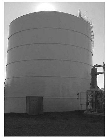
Fig. 3 Liquefied natural gas (LNG) storage tank with remote heat vaporizer in right foreground. Note relief valve stacks on tank top.
Two areas of interest have indicated a definite need for large-volume storage of LNG. First, in transporting gas from energy-rich to energy-poor areas of the world in insulated tankers, the need for large storage depots at both the loading and the market ports is evident. In this case, it is not necessary to preserve the LNG in the tank for long periods, because it is passed on to distribution within a short period. Consequently, higher heat influx resulting in greater boiloff rates can be tolerated, as the vaporized LNG can be used as part of the sendout gas or as fuel.
In the second area, the continued growth and expansion of the natural gas industry have created the necessity for large-volume storage near metropolitan areas to meet winter peak loads that exceed pipeline capacity, also known as peak-shaving. In this case, LNG is stored for relatively long periods and used (i.e., vaporized and distributed) during only a few days of the winter. Consequently, heat influx must be held to a minimum.
Whether the LNG plant is to be used for base-load operation or peak-shaving, a large portion of the cost is the storage facility (Fig. 3). Also, the large volume of storage associated with LNG plants represents a high concentration of energy. It is for these reasons (i.e., economics and reliability) that considerable research and development expenditures have been made relative to storage concepts.
Conventional above-ground, double-wall metal tanks have been used successfully for cryogenic service since the early 1950s. These tanks have generally been flat-bottomed, cylindrical, dome-roof, double-wall tanks with an outer shell of carbon steel or concrete and an inner tank of 9% nickel steel or aluminum that are capable of retaining their strength properties at these cryogenic temperatures. Below — 40°F, the loss of strength properties of carbon steel eliminates it as a suitable LNG containment material. Insulation between the two shells usually consists of perlite in a nitrogen or natural gas atmosphere.
The double-wall, flat-bottomed tank—the conventional configuration for above-ground metal tanks—is really a tank within a tank, with the annular space between the two filled with insulating materials of various types. The inner tank, in contact with the LNG, is made of materials suitable for cryogenic temperatures of — 260°F (— 162°C) and the design loadings of the LNG. The outer tank serves the primary purpose of containing gas pressure and insulating materials that surround the inner tank. The outer tank provides a proven means of protection for the insulation system against external forces, such as fire, impact, and—most important—weather and moisture. The outer tank is vapor-tight, so as to contain the desired internal gas pressure and preclude migration of moisture from the atmosphere into the insulation materials. Connections to the inner tank must pass through the outer tank and are of a special design to permit differential movements due to varying temperature and hydrostatic load.
Liquefied Natural Gas tank foundations must be more carefully designed and constructed than foundations for chemical and petroleum tanks. Limits on construction tolerances and foundation settlements are much more restrictive and important for three reasons:
1. Liquefied Natural Gas tanks are 2-4 times as high (60-120 ft or 18-36 m) as petroleum tanks (30-60 ft or 9-18 m). Any differential foundation settlements can cause the tank to display out-of-roundness and possible uneven liquid levels relative to the tank shells. These conditions are worsened as tank shell heights increase.
2. Internal pressure of LNG tanks requires that the tanks be anchored to the foundations to resist uplift. For anchorage and support of a tank to work properly, the loads must be carried uniformly by the foundations.
3. Load-bearing insulation must be supported uniformly on a nearly flat plane to prevent cracks from forming in the insulation with consequential high heat leak into the LNG.
If the tank foundation is of the ring-wall type, the outer bottom will rest on a gravel or sand base directly upon the soil. Because there is a certain amount of heat migration through the bottom, tank heating coils are installed under the bottom to prevent any soil freezing and consequent frost heaving. In the case of a foundation supported on piles, a minimum 18-in. (460 mm) air space is provided between the ground surface and the bottom of the pile cap to allow for the circulation of air, which eliminates the need for any additional heat source.
In LNG and cryogenic storage systems, insulation is a primary factor. Proper insulation is the key to successful and economical storage. The outer steel shell of the double-wall LNG tank is the best possible vapor barrier against migration of moisture. It permits a gas-tight insulation space where a dry atmosphere can be maintained. This dry atmosphere in a suspended-deck tank is provided by the boiloff from the inner tank.
The insulation material used in double-wall LNG tanks is an inert, inorganic, noncombustible, granular material commonly called perlite. The installed thickness of the perlite governs the overall rate of heat influx through the system. The amount of heat influx into the tank determines the factor commonly called boiloff, which refers to the percentage of the tank’s contents that will evaporate in a given period under specified ambient temperature conditions. The term normal evaporate rate (NER) is sometimes used.
The problem of insulating the space between the tank bottoms is different from that for the annular space between the walls and roof. In the region between the tank bottoms, a load-bearing type of insulation is used. Cellular glass block has proved to be satisfactory for this service, but care must be taken to avoid damaging the somewhat-fragile material during installation and during subsequent periods when tank erection work is under way. Care must also be taken to prevent excessive moisture from penetrating the blocks during construction.
REGASIFICATION/VAPORIZATION
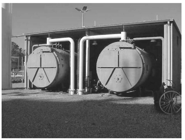
Regasification and sendout of LNG are the final steps in the operation of an LNG peak-shaving plant or import terminal. The regasification or vaporization is accomplished by the transfer of heat to the LNG from ambient air or water, fuel combustion in integral or remote vaporizers (Fig. 4), or recovered waste or process heat. The regasification system, including cryogenic pumps for LNG, must be highly reliable and capable of operating continuously for long periods as well as for brief periods of peak demand.
The cost of the regasification system, also known as the vaporization system, generally represents only a small fraction of the cost of the entire storage plant; however, reliability of the system is most important, because failure or breakdown could result in disruption of service at a crucial time.
The regasification section of a peak-shaving plant may be designed for only a few days of operation during the winter to meet extreme peak loads. To obtain adequate reliability, total sendout capacity may be divided into several independent parallel systems, each capable of handling all or a substantial fraction of the total demand.
Because of the large quantities of liquid and gas being handled and the need for extreme reliability, regasification systems must be engineered carefully. Liquid natural gas, as well as cold vapor, must be prevented from passing into the distribution system. Hydrostatic surge loads must be considered in the liquid piping system. Therefore, instrumentation for process measurement, control, and safety are important considerations.
Fig. 4 Remote boilers used in regasification process.
Regasification requires the following major operations:
1. Pumping LNG from storage to distribution or transmission system pressures.
2. Vaporizing liquid to gas.
3. Controlling process flow, pressure, and temperature.
4. Odorizing and metering the sendout stream.
The physical surroundings, sendout rate, and specific type of LNG facility (base-load as compared with peak-shaving) would determine which method of vaporization is most economical. A base-load plant, which normally would run continuously, can justify a higher investment cost to achieve lower operating cost. On the other hand, with a peak-shaving plant, which would operate for only brief periods during the year, a much lower investment cost would be possible because a higher operating cost is allowable.
The different vaporizers available can be divided into four general categories: (1) integral-heated (fired), (2) remote-heated (fired), (3) ambient-heated, and (4) process-heated.
Although the design and economic considerations discussed above are important in the selection of equipment for base-load operation and peak shaving, the requirement for base-load continuous service is perhaps the most critical. Care must be exercised in evaluating vaporizer and pump performance in peak-shaving plants, where the service period ranges from days to weeks per year. Base-load LNG plant equipment must have service reliability in excess of 8000 h per year. This requires that special consideration be given to such items as bearing life in pumps and selection of materials in hot or corrosive areas, such as combustion zones or those exposed to products of combustion.
There is increased interest in floating and other offshore LNG liquefaction plants, and proposals have been developed for floating or offshore LNG import terminals as a solution to siting problems in the United States. Requirements for base-load operation offshore are similar to those for onshore operation, although compactness, safety, reliability, and low maintenance may be even more critical. Because power generation is inherently required for offshore facilities, the recovery of gas turbine or power generation waste heat is available for supplemental vaporization, along with the primary seawater, although the trade-off of complexity vs efficiency must be analyzed.
If all the low-temperature source available at a base-load receiving terminal could be used effectively over the entire temperature range from — 260°F (—162°C), the value of the refrigeration would approach the initial cost of liquefaction. It is not practical to recover all the cold, but a large number of schemes have been proposed or installed to take partial advantage of the refrigeration available, which leads to reduced vaporization cost.
An example of a cryogenic recovery or cold utilization vaporizer system is one that would appeal to total-energy companies or utilities that supply both natural gas and electrical power. The gas source would be LNG, and the power would be generated with gas-fired turbines.
The process can be described as having the following features:
1. The production of horsepower by means of a gas-fired turbine driver.
2. The continuous vaporization of LNG with the large quantity of low-quality heat available from the gas-fired turbine exhaust.
3. The use of LNG or low-temperature natural gas for the purpose of precooling the inlet combustion air to the turbine, thereby increasing the power output of the generator.
The Eco-Electrica LNG plant in Puerto Rico has installed such a system for the purpose of generating electrical power for offsite consumption. The idea has been widely studied and appears to have merit.
Although the sendout or regasification section of an LNG storage facility is one of the least costly plant elements, it is probably the most important, because if it should fail to operate on the few occasions when it is called upon for peak demand, the entire purpose will have been defeated. When peak demands occur, the regasifica-tion system must be ready to operate immediately and reliably. Fuel gas for regasification typically uses about 1.5%-2% of the facility throughput of natural gas.
In a base-load plant, which is designed to operate a full 365 days per year, interruption of the regasification section has equally serious consequences. A base-load import terminal is just one critical link in the import chain from gas production and liquefaction to shipping and terminal operation. Failure of any link leads to an interruption of gas supplies and may involve high costs of “take or pay” contract provisions to protect the investment in such capital-intensive projects from loss of income during periods of unscheduled downtime.
TRANSPORTATION
All LNG is transported in one manner or another, whether a distance of a few hundred feets by pipeline from liquefaction to storage or several thousand miles between countries by ocean tankers. For intermediate distances, specially designed pipelines are used for loading and unloading LNG tankers, and have been proposed for transporting LNG greater distances overland. Liquefied Natural Gas has been transported by tanker truck in the United States for several years. For transportation of larger quantities of LNG, barges designed for use on inland waterways and for use on the open seas have been proposed. All these modes of transportation can be classified into two broad categories: marine transportation and overland transportation.
Marine transport of LNG has advanced considerably since the first LNG cargo ship technology was developed in the late 1950s and early 1960s. Since that time, a large number of LNG containment systems has been studied and developed. The early designs that were commercialized have proved to be safe, reliable systems for marine transport of LNG. In addition, new designs and system modifications are under development and greatly benefit from the use of vacuum-jacketed LNG storage tanks in lieu of external insulation.
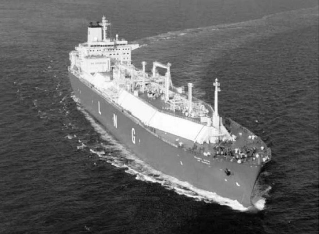
Liquefied Natural Gas ship (Fig. 5) size is spoken of in terms of cubic meter of total liquid capacity. Therefore, ship size will be given in cubic meter of liquid only (1m3 equals 35.31 ft3 or 6.29 bbl liquid). Liquefied Natural Gas tankers range in size from about 5000 m3 for the early pioneering designs to the 125,000-145,000 m3 ships that have become the industry standard. Ships of 165,000 m3 have been designed, and a 330,000 m3 ship has been proposed. Most ships are constructed in Korea at this time.
Typically, LNG tankers are loaded directly by cryogenic pumps from the onshore storage tanks. During loading, excess vapor is generated within the cargo tanks, while the dropping liquid level in the storage tank results in a need for vapor to prevent creation of a vacuum; therefore, excess vapor from the cargo tanks is returned to the storage tank via an insulated vapor return line. Excess vapor may be absorbed by the system, consumed for fuel, or vented to the atmosphere. Unloading is accomplished in a similar manner through the use of submerged cargo pumps within the cargo tanks.
Liquefied Natural Gas can be transported overland in pipelines or mobile tanks. Historically, short-distance, large-volume transport has been through insulated pipelines, as from liquefaction plant to storage or in loading and unloading tankers. Smaller volumes can be moved over longer distances in insulated over-the-road trucks or railway cars. Periodically, long-distance LNG pipelines have been proposed but have been rejected due to the high cost of sufficiently efficient insulation systems.
Prior to 1969, only a few small-scale over-the-highway movements of LNG had been attempted in this country using equipment originally designed for liquid nitrogen service. Based on the success of these initial operations and the increasing need for highway transport of LNG, new equipment designed and built specifically for LNG service became commercially available for the first time in the early 1970s. This equipment is produced by companies that have long provided trailers for the industrial gas industry. The design of this new equipment was based on well-matured cryogenic technology, and incorporated reliability and safety concepts developed through years of experience in transporting liquid nitrogen and oxygen.
Fig. 5 Liquefied natural gas (LNG) transport ship.
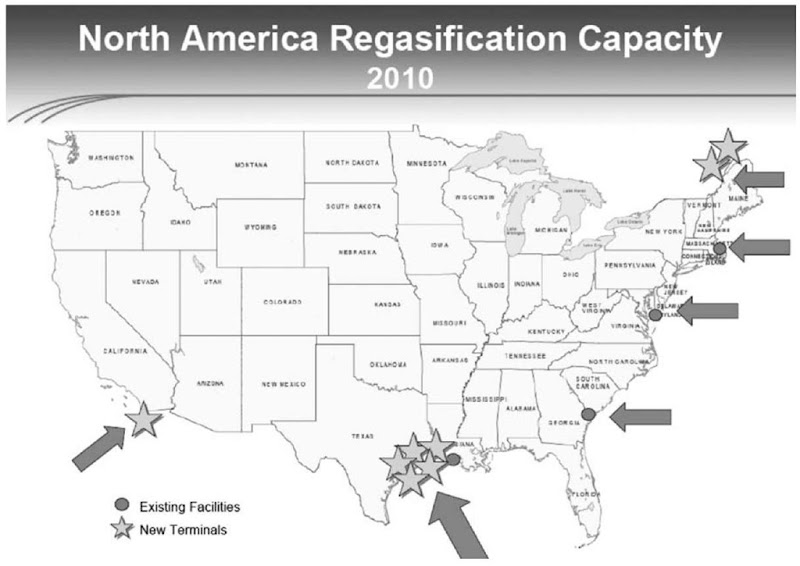
Fig. 6 These new facilities will play a vital role in meeting existing and projected natural gas demands.
In the ensuing years, the widespread highway movement of LNG has become commonplace and has established an enviable record of safety and reliability.
CONCLUSION
The LNG industry has been a key player in the U.S. natural gas supply system since the early 1960s, used primarily in a peak-shaving role. It has been proved that the liquefaction, transportation, storage, and regasification of stranded resources of natural gas constitute an economically feasible solution to declining domestic production and resulting price volatility due to constrained supplies and increasing demand—all this with an enviable safety record.
Based on predictions by Cheniere Energy (www. cheniere.com), the next phase in the maturing of the U.S. Liquefied Natural Gas industry will be in the base-load import terminal area. Currently, 17 liquefaction export plants and more than 150 LNG marine tankers are operating around the world. With more than 25 new liquefaction export terminals proposed to be built prior to 2010 and more than 100 marine vessels slated for delivery before 2008, the stability of the LNG commodity trading market is becoming more secure with each passing day.
The current bottleneck in the U.S. market is receiving capacity. Fig. 6 shows existing and proposed new U.S. import terminals with projected completion dates prior to 2010. Public education and acceptance play a key role in market development.
“Our limited capacity to import liquefied natural gas effectively restricts our access to the world’s abundant supplies of natural gas.” (Alan Greenspan, U.S. Federal Reserve Bank chairman, May 21, 2003)
“What we need to do is get in place, as soon as we can, the capability of fairly substantial imports that enable our manufacturers who use natural gas to compete internationally.” (Alan Greenspan, U.S. Federal Reserve Bank chairman, April 21, 2004)
