Abstract
Heat pumps capture heat energy from low-grade heat sources, such as ambient air and waste heat streams, and upgrade to a higher temperature level for useful applications. This entry includes a brief history, fundamentals, classifications, applications, and performance parameters of heat pumps. Working principles of the thermoelectric heat pump, the absorption heat pump, the gas compression heat pump, and the vapor compression heat pump are explained. Performance parameters of the heat pump systems are presented: coefficient of performance, energy efficiency ratio, primary energy ratio, and ambient energy fraction.
INTRODUCTION
This entry aims to provide foundation knowledge about heat pumps for both professional and nonprofessional readers. A brief history of heat pumps, basic terms used in the heat pump industry and research, and the fundamentals of heat pumps are presented. Working principles of the thermoelectric heat pump, the absorption heat pump, the gas compression heat pump, and the vapor compression heat pump are explained by using schematic diagrams. Performance parameters of the heat pump systems— coefficient of performance (COP), energy efficiency ratio (EER), primary energy ratio (PER), and ambient energy fraction (AEF)—are also discussed.
Major advances have been made in heat pump technologies over the past 30 years. Heat pumps in their various and diverse forms allow one to harness, in a cost-effective manner, solar energy that has already been stored in the atmosphere and biosphere. To make a fair systematic comparison with other systems that provide the same thermal output, AEF may be used. The concept and the method of estimating the AEF are discussed. The relationships among the AEF, the heating coefficient of performance (HCOP), and PER are also presented.
Brief History
Although most people are familiar with the common household refrigerator, the concept of using such a device to provide heating rather than cooling is less widely understood. The basic operational principle of this machine called heat pump, however, was laid down in thermodynamic terms by Lord Kelvin, the first professor of natural philosophy at the University of Glasgow,
Scotland in the middle of the 19th century. Whereas the thermodynamic principle of the heat pump was found in 1852, it was not until 1855 that it was realized for producing heat by means of an open-cycle mechanical vapor recompression unit in Ebensee, Austria.[1] Much later, the closed vapor compression process was used for generating useful heat. After World War II, heat pump units for air conditioning homes and individual rooms became common. Now heat pump technology is well known as one of the energy conservation technologies.
Fundamentals
A heat pump is a thermodynamic system whose function is to heat at the required temperature with the aid of heat extracted from a source at lower temperature.[2] Heat pumps are devices designed to utilize low-temperature sources of energy that exist in atmospheric air, lake or river water, and in the earth. These sources are referred to as ambient energies. Heat pumps can also be operated using waste heat from commercial and industrial processes and thereby upgrading this to the required temperature level for some thermal process operations.[3]
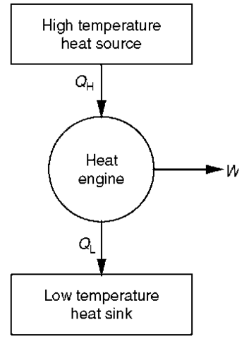
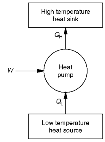
The heat pump can be considered to be a heat engine in reverse.[4] A heat engine removes heat from a high-temperature source and discharges heat to a low-temperature sink, and in doing so can deliver work (see Fig. 1). Heat pumps capture heat energy from low-grade sources and deliver at a higher temperature. They require external work (W) to upgrade the heat absorbed (QL) (see Fig. 2). Note the heat energy flows from a low-temperature heat source to a higher application temperature. This is reverse to the natural flow direction of heat from a higher temperature to a lower temperature. For ideal conditions without heat losses the energy balance of a heat pump provides (Eq. 1):
Fig. 1 Thermodynamic model of heat engine.
where QH, useful heat delivered; gL, heat absorbed; W, work input.
The useful heat delivered is always greater than the work input to the heat pump for ideal conditions.
The technical and economic performance of a heat pump is closely related to the characteristics of the heat source. Table 1 lists current commonly used heat sources. Ambient and exhaust air, soil, and ground water are practical heat sources for small heat pump systems, whereas sea/lake/river water, rock (geothermal), and waste water are used for large heat pump systems.[5]
The fundamental theories of heat pumps and refrigerators are the same. In engineering practice, a distinction is made between heat pumps and refrigerators. The principal purpose of the latter devices is to remove heat from a low-temperature heat source, and the purpose of the former device is to supply heat to a high-temperature sink. In many practical devices, the heating and cooling elements are interchangeable. The term reverse cycle air conditioner is frequently applied to heat pumps with interchangeable heating and cooling elements. In Japan and in the United States, reversible air-conditioning units are called heat pumps, and in Europe, the term heat pump is used for heating-only units.[1]
Fig. 2 Energy flow of a heat pump.
Table 1 Commonly used heat sources
| Heat source | Temperature range (°C) |
| Ambient air | -10 to 15 |
| Building exhaust air | 15-25 |
| Ground water | 4-10 |
| Lake water | 0-10 |
| River water | 0-10 |
| Sea water | 3-8 |
| Rock | 0-5 |
| Ground | 0-10 |
| Waste water and effluent | > 10 |
Carnot Coefficient of Performance (Theoretical COP)
The heating performance of a heat pump is measured by HCOP. The HCOP is the ratio of the quantity of heat transferred to the high-temperature sink to the quantity of energy driving the heat pump (see Fig. 2).
In the Carnot ideal heat pump cycle, the heat is delivered isothermally at TH and received isothermally at By using the laws of thermodynamics and definition of entropy, it can be shown that the Carnot heating coefficient of performance is given by Eq. 3.
No practical heat pump constructed can have a better performance than this theoretical ideal HCOP. All that our practical heat pump cycles can do is struggle toward achieving this performance.1-4-1
Facts About Heating Relevant to Heat Pumps
It is argued that heat pumps are very energy efficient and, therefore, environmentally benign. The IEA heat pump centre provides the basic facts about heat supply and discusses the value of heat pumps.[6] The basic facts about heating explained are
• Direct combustion to generate heat is never the most efficient use of fuel.
• Heat pumps are more efficient because they use renewable energy in the form of low-temperature heat.
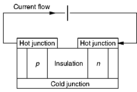
Fig. 3 Schematic of thermoelectric heat pump.
• If the fuel used by conventional boilers were redirected to supply power for electric heat pumps, about 35%-50% less fuel would be needed, resulting in 35%-50% less emissions.
• Around 50% savings are made when electric heat pumps are driven by combined heat and power (CHP) or cogeneration systems.
• Whether fossil fuel, nuclear energy, or renewable power is used to generate electricity, electric heat pumps make far better use of these resources than do resistance heaters.
• The fuel consumption and, consequently, the emissions rate of an absorption or gas-engine heat pump are about 35%-50% less than those of a conventional boiler.
Because heat pumps consume less primary energy than conventional heating systems, they are an important technology for reducing the unwanted air pollutants that harm the human environment, such as respirable particulate matters (PM), carbon monoxide (CO), nitrogen oxides (NO*), sulphur dioxide (SO2), and carbon dioxide (CO2).
HEAT PUMP TYPES
Four major types of heat pumps may be identified in the literature.[7] These are
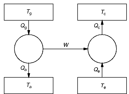
Fig. 4 Thermodynamic model of absorption heat pump.
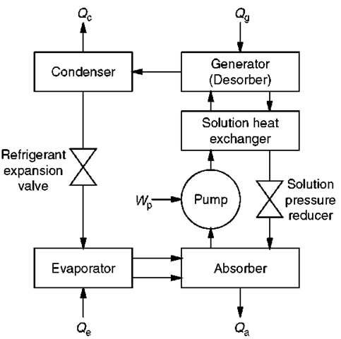
Fig. 5 Simple absorption cycle.
• The thermoelectric heat pump
• The absorption heat pump
• The gas compression heat pump
• The vapor compression heat pump
The Thermoelectric Heat Pump
The thermoelectric heat pump uses the Peltier effect. Two materials with different thermoelectric properties (p type and n type) are arranged to form hot and cold junctions, and are connected in series with a direct-current voltage source (Fig. 3). These devices do not have moving parts, and the cooling and heating elements may be reversed simply by changing the direction of the current.
The Absorption Heat Pump
All absorption cycles include at least three thermal exchanges with their surroundings (i.e., energy exchange at three different temperatures). For the system to operate, the generator temperature (Tg) must be greater than the condenser temperature (Tc) and the absorber temperature (ra), which in turn must be greater than the evaporator temperature (Te). An absorption cycle is a heat-activated thermal cycle. The absorption heat pump can be considered as a heat engine driving a heat pump (see Fig. 4).
The components of a simple single-effect absorption system are
• Generator (desorber)
• Condenser
• Refrigerant expansion valve
• Evaporator
Fig. 6 Schematic of gas compression heat pump.
• Absorber
• Pump
• Solution heat exchanger
• Solution pressure reducer
• Connecting pipes
The absorption system utilizes a sorbent-refrigerant pair. The widely used pairs are Lithium-bromide and water, and water and ammonia. A schematic of the continuous absorption heat pump system is shown in Fig. 5. An absorption cycle is a heat-activated thermal cycle. The major exchanges with its surroundings are thermal energy. A small amount of mechanical work is required at the pump to transport the working fluids.
A high-temperature heat source supplies heat to the generator to drive off the refrigerant vapor from solution. The condenser receives the refrigerant vapor from the generator. In the condenser, the refrigerant changes phase from vapor to liquid, and heat is rejected at a medium temperature. The refrigerant expansion valve reduces the pressure of the refrigerant from the condensing pressure to the evaporating pressure. In the evaporator, the liquid refrigerant collects the low-temperature heat and changes to vapor phase. In other words, the working fluid (refrigerant) provides the cooling effect at the evaporator, and the vaporized refrigerant enters the absorber. The strong-concentration sorbent absorbs the refrigerant vapor and becomes a weak solution. Note the heat rejected at the absorber. The low-pressure weak solution (refrigerant and sorbent) is pumped to the solution heat exchanger to exchange heat with the strong-concentration sorbent. The solution pressure reducer accepts the high-pressure strong solution from the generator and delivers low-pressure strong solution to the absorber. The generator receives the high-pressure weak solution from the solution heat exchanger, and separates the refrigerant and sorbent.
The Gas Compression Heat Pump
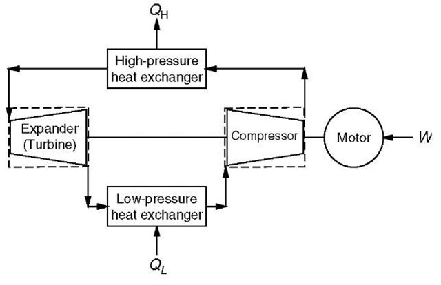
Gas compression heat pumps use a gas as the working fluid. Phase changes do not occur during the cycle of
operation. Major components of a gas compression heat pump system are:
• Gas compressor
• High-pressure heat exchanger
• Gas expander (or turbine)
• Drive motor
• Low-pressure heat exchanger
A schematic of a gas compression heat pump is shown in Fig. 6. The gas is drawn into the compressor and heated. The heated high-pressure gas delivers heat at the high-pressure heat exchanger. At the expander (turbine), high-pressure gas does the expansion work that helps drive the compressor. In general, the external work input to the compressor is provided by a drive motor.
The Vapor Compression Heat Pump
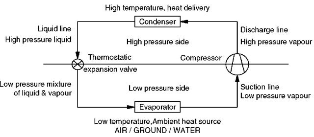
Almost all heat pumps currently in operation are based on either a vapor compression or an absorption cycle.[8] Heat pumps and refrigerators of the vapor compression type utilize a working fluid that undergoes phase changes during operation. The phase changes occur principally during the heat collection and rejection stages of the cycles. The phase-changing processes occurring in the vapor compression heat pumps are accompanied by extremely favorable heat transfer conditions. Boiling agitation in evaporators and dropwise condensation in condensers make the heat transfer rates very high. To carry out evaporation and condensation, any practical heat pump uses four separate components, as illustrated in Fig. 7:
• Compressor
• Condenser
• Expansion device
• Evaporator
The compressor is the heart of the vapor compression heat pump system. By using mechanical power, the compressor increases the pressure of the working fluid vapor received from the evaporator and delivers it to the condenser. The working fluid condenses and provides useful heat at the condenser. The pressure of the liquid working fluid coming out of the condenser is reduced to the evaporating pressure by an expansion device. The low-grade heat is collected at the evaporator, and the phase of the working fluid changes from liquid to vapor. The working fluid enters the compressor in vapor form to repeat the cyclic flow.[9]
Compressors used in practical units are generally of the positive displacement type: either reciprocating or rotary vanes. In practice, nearly all vapor compression heat pumps use thermostatic expansion valves (T-X valves) because of the availability of the valve to handle a wide range of operating conditions and because of the fact that the pressure reduction is essentially isenthalpic. These valves, which are relatively low-cost devices, control the liquid working fluid flow to the evaporator by sensing the superheated condition of the working fluid leaving the evaporator. Such control ensures that nearly all the available evaporator surface is covered with a forced convection nucleate boiling film with consequential excellent heat transfer characteristics in the evaporation process.
Fig. 7 Schematic diagram of vapor compression heat pump.
Reversible circuit heat pumps for building cooling and heating are equipped with a four-way exchange valve that can be operated automatically or manually. This valve enables the normal evaporator to become the condenser and the normal condenser to become the evaporator so that the machine can be made to operate in reverse fashion. This arrangement is often incorrectly called a reverse-cycle operation because of the end effect achieved—i.e., the interchange of roles for the cooling and heating parts of the circuit. It would be better to call this a reverse-flow operation, as the basic thermodynamic cycle remains the same for each mode of operation.
In general, vapor compression heat pumps are classified in many ways. One method commonly used distinguishes among air, water, and ground sources of low-temperature energy and also between the high-temperature energy delivery medium (i.e., air or water). In such a classification, the most common types of heat pump units would include air to air units and water to water units. Solar energy could also be captured at the evaporator as a heat source. These types of heat pumps are called solar-assisted and sola-boosted heat pumps.[10]
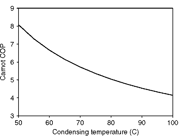
Fig. 8 Effect of condensing temperature on ideal COP (evaporating temperature = 10°C).
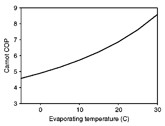
Changes in condensing and evaporating temperatures affect the work done at the compressor, and, consequently the COP. Decreasing the condenser or increasing the evaporator temperatures will decrease the compressor work and increase the COP. Fig. 8 shows the effect of condensing temperature on COP for a fixed evaporator temperature. The effect of the evaporating temperature on the COP for a fixed condenser load temperature is shown in Fig. 9. For simplicity, these curves have been obtained assuming operation on the ideal heat pump cycle—i.e., the Carnot cycle of two isothermal and two isentropic (reversible adiabatic) processes not allowing any practical deviations. Although the COP values for real machines will be substantially lower, the trend will be the same.
PERFORMANCE PARAMETERS
This section defines and explains some performance parameters that are used to compare various heat pumps for a particular application, and also presents the relationships among them.
Fig. 9 Effect of evaporating temperature on ideal COP (condensing temperature = 70°C).
Coefficient of Performance and Energy Efficiency Ratio
System coefficient of performance (SCOP) is defined as output heating capacity per unit of power input to the system (see Eq. 4).
System coefficient of performance is a dimensionless number that measures the performance of a heat pump. If the heating capacity is expressed in units other than W, it is called the heating energy efficiency ratio (HEER). Heat pumps sold in the United States are often stated in terms of EER (see Eq. 5).
In the equation described, EER has a unit of Btu/h per W. It should be noted that 1 Btu/h = 0.2928 W. Therefore, the relationship between EER and COP can be expressed as in Eq. 6.
In the equation described, EER has a unit of Btu/h per W. It should be noted that 1 Btu/h = 0.2928 W. Therefore, the relationship between EER and COP can be expressed as in Eq. 6.
Primary Energy Ratio
The HCOP provides a measure of the usefulness of the heat pump system in producing large amounts of heat from a small amount of work. It does not express the fact that energy available as work is normally more useful than energy available as heat. To assess different heat pump systems using compressor drives from different fuel or energy sources, the PER is applied. The PER takes into account not only the heat pump COP, but also the efficiency of conversion of the primary fuel into the work that drives the compressor. Primary energy ratio is defined as in Eq. 7.[4] This also can be expressed as in Eq. 8,
where QH=load, £pe = primary energy used by the heat pump system, and rjpp = power plant efficiency.
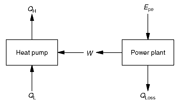
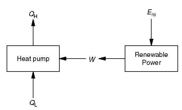
The drive energy of heat pumps is most commonly electricity. “Ideally, a heat pump where free work is available should be contemplated, e.g., wind or water power.”[4] Consider an electric heat pump powered by a conventional power plant fuelled by a nonrenewable energy source (see Fig. 10). The power-plant efficiency, ?7pp, is up to 58% for oil- or gas-fired combined-cycle power plants currently available on the market. The PER is equal to the HCOP for direct power generation from renewable ambient energy sources, such as solar and wind.[1] This concept is illustrated in Fig. 11.
Fig. 10 Energy flow of a conventional electric heat pump.
The amount of renewable or ambient energy spent (used up) to produce work for the heat pump is equal to the amount of work (i.e., £re = W)—for this case, by definition ?7pp= 1.[1] It should be noted that unlike the losses in a fossil-fuel power plant, the unused ambient energy passing through the renewable power plant is still in the form of ambient energy, and it is available to be used.
Ambient Energy Fraction
To make a fair systematic comparison of heat pumps and other systems that provide the same heat output, the term AEF was developed by Aye et al.[11] The term solar fraction is widely understood, accepted, and used in the solar energy field. It is defined as the fractional reduction of purchased energy when a solar energy system is used.[12] It is the fraction of the load contributed by the solar energy, which can be calculated by Eq. 9,
Fig. 11 Energy flow of a renewable electric heat pump.
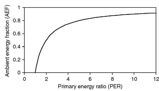
Fig. 12 The ambient energy fraction vs the primary energy ratio.
where L, the load; E, the auxiliary energy supplied to the solar energy system; and Ls, the solar energy delivered.
Similar to the solar fraction of a solar system, the term AEF of a heat pump can be defined as the fraction of the load contributed by the ambient energy, which may be calculated as in Eq. 10.
Table 2 Ambient energy fractions of a heat pump powered by typical power plants
Fig. 12 illustrates the relationship between the AEF and the PER.
Table 2 shows the AEFs of a heat pump, which has an HCOP of 3.5, for various electric power plants. Table 2 clearly shows that for the same heat pump, the AEF may vary from 1 to 71%, depending on how electricity is generated for driving the heat pump compressor. The AEF for the renewable electricity-driven heat pump is the highest (71%). The renewable energy used is only 29% (i.e., 100%-71%) of the total thermal load. The energy use of the brown-coal electricity-driven heat pump is 99% of the total thermal load (i.e., 0.99 MJ of brown-coal energy is required for 1 MJ of thermal load). Table 3 shows the effect of heat pump COP on the AEF of a heat pump powered by a renewable source.
HEAT PUMP APPLICATIONS
Heat pumps have been used for domestic, commercial, and industrial applications.
Domestic applications are:
• Provision of space heating
• Provision of hot water
• Swimming-pool heating
Table 2 Ambient energy fractions of a heat pump powered by typical power plants
| Gas-fired | |||||
| Power plant | Brown coal | Nuclear | Black coal | combined-cycle | Renewable |
| Power plant | 0.29a | 0.33b | 0.35a | 0.58b | 1.00 |
| efficiency, 7jpp | |||||
| HCOP of heat | 3.50 | 3.50 | 3.50 | 3.50 | 3.50 |
| pump | |||||
| Primary energy | 1.02 | 1.16 | 1.23 | 2.03 | 3.50 |
| ratio, PER | |||||
| Ambient energy | 0.01 | 0.13 | 0.18 | 0.51 | 0.71 |
| fraction, AEF | |||||
“Typical Australian data
Table 3 Effect of HCOP on AEF of a heat pump powered by renewable source
| HCOP of heat pump | 1.50 | 2.50 | 3.50 | 4.50 |
| Renewable power plant efficiency, 7jpp | 1.00 | 1.00 | 1.00 | 1.00 |
| Primary energy ratio, PER | 1.50 | 2.50 | 3.50 | 4.50 |
| Ambient energy fraction, AEF | 0.33 | 0.60 | 0.71 | 0.78 |
Commercial and industrial applications are
• Space heating
• Water heating
• Swimming-pool heating
• Drying and dehumidification
• Evaporation and boiling Desalination
CONCLUSION
The fundamentals of heat pumps were presented together with the working principles of the thermoelectric heat pump, the absorption heat pump, the gas compression heat pump, and the vapor compression heat pump. It should be noted that vapor compression heat pumps driven by electricity dominate the current market. Heat pumps are very energy efficient and, therefore, environmentally benign compared with other available heating technologies. The technical and economic performance of a heat pump is closely related to the characteristics of the heat source.
Various performance parameters are available for comparisons of heat pumps; HCOP and energy efficiency ratio are the most widely used. Primary energy ratio and AEF can be used to compare various heat pump systems systematically and fairly. The AEF of an electric heat pump depends on the HCOP and the power plant efficiency based on the primary energy used. The AEF is highly dependent on the type of power plant used to generate the electricity that drives the heat pump compressor. Heat pumps driven by renewable electricity offer the possibility of reducing energy consumption significantly. In the future, the AEF may be used widely as a performance parameter of heat pumps, because energy-resource issues are becoming more important.

