Abstract
Every piece of energy-consuming equipment has some form of control system associated with it. This article provides information about electronic control systems primarily used to control HVAC equipment. The same principles are used to control other equipment, such as lighting, compressed air systems, process equipment, and production equipment.
INTRODUCTION
Every piece of energy-consuming equipment has some form of control system associated with it. The controls can be as simple as a snap switch or as complicated as a dedicated microcomputer chip system. Larger pieces of equipment, along with buildings and industrial processes, typically use complex computer-based control systems to optimally control and operate them. This article provides information about electronic control systems primarily used to control HVAC equipment. However, the same technologies and principles are used to control other equipment, such as lighting, compressed air systems, process equipment and production equipment.
An electronic control system comprises a sensor, controller and final control element. The sensors used in electronic control systems are simple, low-mass devices that provide stable, wide-range, linear and fast response. The electronic controller is a solid-state device that provides control over a discrete portion of the sensor range and generates an amplified correction signal to control the final control element.
Features of electronic control systems include the following:
• Controllers can be remotely located from sensors and actuators.
• Controllers can accept a variety of inputs.
• Remote adjustments for multiple controls can be located together, even though sensors and actuators are not.
• Electronic control systems can accommodate complex control and override schemes.
• Universal type outputs can interface to many different actuators.
• Display meters can indicate input or output values.
The sensors and output devices (e.g., actuators, relays) used for electronic control systems are usually the same ones used on microprocessor-based systems. The distinction between electronic control systems and microprocessor-based systems is in the handling of the input signals. In an electronic control system, the analog sensor signal is amplified, then compared to a setpoint or override signal through voltage or current comparison and control circuits. In a microprocessor-based system, the sensor input is converted to a digital form, in which discrete instructions (algorithms) perform the process of comparison and control.
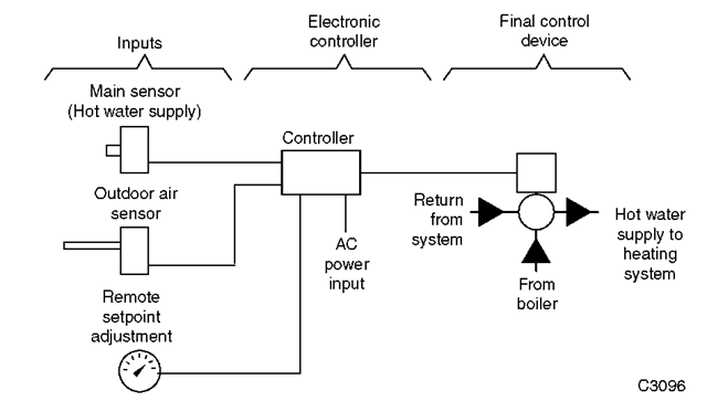
Fig. 1 shows a simple electronic control system with a controller that regulates supply water temperature by mixing return water with water from the boiler. The main temperature sensor is located in the hot water supply from the valve. To increase efficiency and energy savings, the controller resets the supply water temperature setpoint as a function of the OA (outdoor air) temperature. The controller analyzes the sensor data and sends a signal to the valve actuator to regulate the mixture of hot water to the unit heaters. These components are described in the section titled “Components.”
A glossary of control system terms is given in the last section of this article.
Electronic control systems usually have the following characteristics:
Controller. Low voltage, solid state. Inputs. 0-1 V d.c., 0-10 V d.c., 4-20 mA, resistance element, thermistor, thermocouple. Outputs. 2-10 V d.c. or 4-20 mA device. Control Mode. Two-position, proportional, proportional plus integral (PI) or step.
Fig. 1 Basic electronic control system.
Circuit diagrams in this article are basic and fairly general. A resistance-temperature input and a 2-10 V d.c. output are used for purposes of discussion. A detailed discussion on control modes can be found in the “Control Fundamentals” section of the Engineering Manual of Automatic Controls.[1]
ELECTRONIC CONTROL SYSTEM COMPONENTS
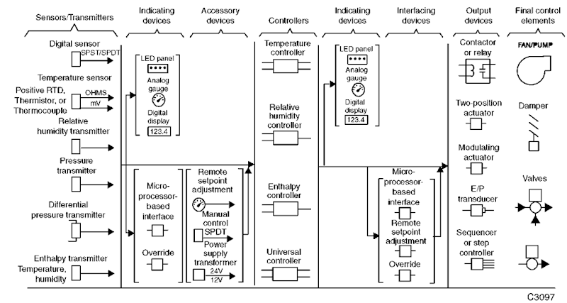
An electronic control system includes sensors, controllers, output devices such as actuators and relays; final control elements such as valves and dampers; and indicating, interfacing, and accessory devices. Fig. 2 provides a system overview for many electronic system components.
Sensors
A sensing element provides a controller with information concerning changing conditions. Analog sensors are used to monitor continuously changing conditions such as temperature or pressure. The analog sensor provides the controller with a varying signal such as 0-10 V. A digital (two-position) sensor is used if the conditions represent a fixed state such as a pump that is on or off. The digital sensor provides the controller with a discrete signal such as open or closed contacts.
Fig. 2 Typical electronic control system components.
Some electronic sensors use an inherent attribute of their material (e.g., wire resistance) to provide a signal and can be directly connected to the electronic controller. Other sensors require conversion of the sensor signal to a type or level that can be used by the electronic controller. For example, a sensor that detects pressure requires a transducer or transmitter to convert the pressure signal to a voltage that can be used by the electronic controller. Typical sensors used in electronic control systems are included in Fig. 2. A sensor-transducer assembly is called a transmitter.
Temperature Sensors
For electronic control, temperature sensors are classified as follows:
• Resistance temperature devices (RTDs) change resistance with varying temperature. RTDs have a positive temperature coefficient (resistance increases with temperature).
• Thermistors are solid-state resistance-temperature sensors with a negative temperature coefficient.
• Thermocouples directly generate a voltage as a function of temperature.
Resistance Temperature Devices
In general, all RTDs have some common attributes and limitations:
• The resistance of RTD elements varies as a function of temperature. Some elements exhibit large resistance changes, linear changes, or both over wide temperature ranges.
• The controller must provide some power to the sensor and measure the varying voltage across the element to determine the resistance of the sensor. This action can cause the element to heat slightly—called self-heating—and can create an inaccuracy in the temperature measurement. By reducing the supply current or by using elements with higher nominal resistances, the self-heating effect can be minimized.
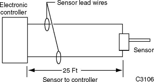
• Some RTD element resistances are as low as 100 Q. In these cases, the resistance of the lead wires connecting the RTD to the controller may add significantly to the total resistance of the connected RTD, and can create an offset error in the measurement of the temperature. Fig. 3 shows a sensor and controller in relation to wire lead lengths. In this figure, a sensor 25 ft from the controller requires 50 ft of wire. If 18 AWG solid copper wire with a d.c. resistance of 6.39 Q/Mft is used, the 50 ft of wire has a total d.c. resistance of 0.319 Q. If the sensor is a 100-ohm platinum sensor with a temperature coefficient of 0.69 Q/°F, the 50 ft of wire will introduce an error of 0.46°F. If the sensor is a 3000-ohm platinum sensor with a temperature coefficient of 4.8 Q/°F, the 50 ft of wire will introduce an error of 0.066°F.
Fig. 3 Lead wire length.
Significant errors can be removed by adjusting a calibration setting on the controller, or—if the controller is designed for it—a third wire can be run to the sensor and connected to a special compensating circuit designed to remove the lead length effect on the measurement. In early electronic controllers, this three-wire circuit was connected to a Wheatstone Bridge configured for lead wire compensation. In digital controllers, lead wire compensation on low resistance sensors may be handled by software offset.
• The usable temperature range for a given RTD sensor may be limited by non-linearity at very high or low temperatures.
• RTD elements that provide large resistance changes per degree of temperature reduce the sensitivity and complexity of any electronic input circuit. (Linearity may be a concern, however.)
A sensor constructed using a BALCO wire is a commonly used RTD sensor. BALCO is an annealed resistance alloy with a nominal composition of 70 percent nickel and 30 percent iron. A BALCO 500-ohm resistance element provides a relatively linear resistance variation from — 40 to 250°F. The sensor is a low-mass device and responds quickly to changes in temperature.
Another material used in RTD sensors is platinum. It is linear in response and stable over time. In some applications, a short length of wire is used to provide a nominal resistance of 100 Q. However, with a low resistance value, the element can be affected by self-heating and sensor-leadwire resistance. Additionally, due to the small amount of resistance change of the element, additional amplification must be used to increase the signal level.
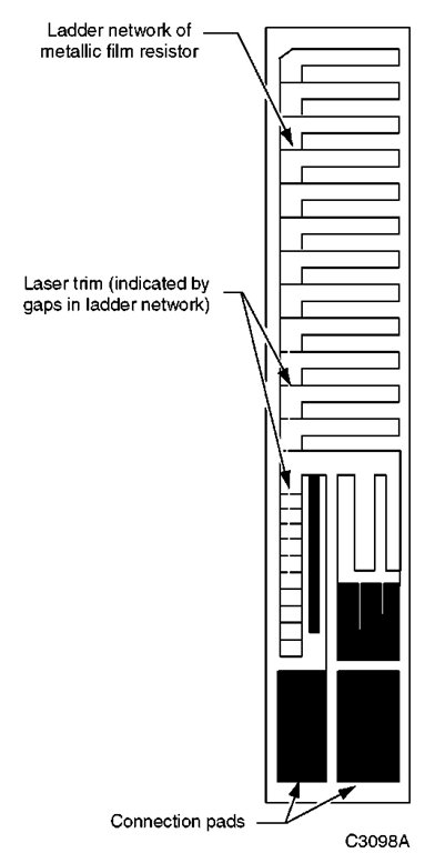
To use the desirable characteristics of platinum and minimize any offset, one manufacturing technique deposits a film of platinum in a ladder pattern on an insulating base. A laser trimming method (Fig. 4) then burns away a portion of the metal to calibrate the sensor, providing a resistance of 1000 Q at 74°F. This platinum film sensor provides a high resistance-to-temperature relationship. With its high resistance, the sensor is relatively immune to self-heating and sensor-leadwire resistance offsets. In addition, the sensor is an extremely low-mass device and responds quickly to changes in temperature. RTD elements of this type are common.
Fig. 4 Platinum element RTD sensor.
Solid-State Resistance Temperature Devices
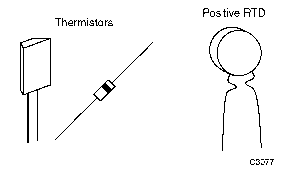
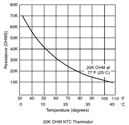
Fig. 5 shows examples of solid-state resistance temperature sensors having negative and positive temperature coefficients. Thermistors are negative temperature coefficient sensors typically enclosed in very small cases (similar to glass diodes or small transistors) that provide quick response. As the temperature increases, the resistance of a thermistor decreases (Fig. 6). Selection of a thermistor sensor must consider the highly nonlinear temperature-resistance characteristic.
Fig. 5 Solid-state temperature sensors.
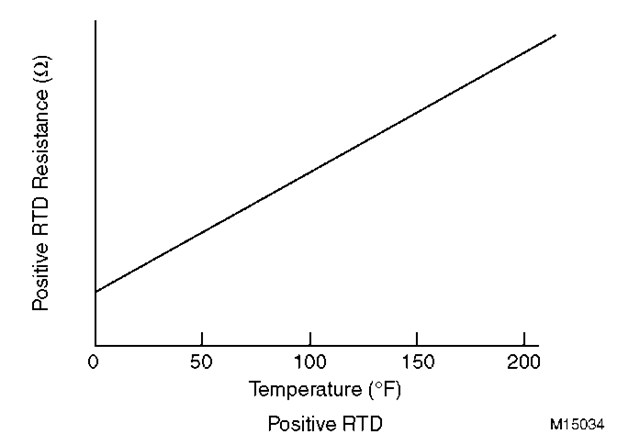
Positive temperature coefficient solid-state temperature sensors may have relatively high resistance values at room temperature. As the temperature increases, the resistance of the sensor increases (Fig. 6). Some solid-state sensors have near-perfect linear characteristics over their usable temperature range.
Fig. 6 Resistance vs temperature relationship for solid-state sensors.
Fig. 7 Basic thermocouple circuit.
Thermocouples
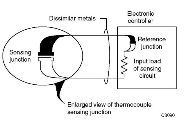
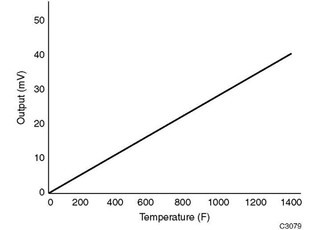
In a thermocouple, two dissimilar metals such as iron and constantan are welded together to form a thermocouple junction (Fig. 7). When this junction is exposed to heat, a voltage in the millivolt range is generated and can be measured by the input circuits of an electronic controller. The amount of voltage generated is directly proportional to the temperature (Fig. 8). At room temperatures for typical HVAC applications, these voltage levels are often too small to be used, but are more usable at higher temperatures of 200°F-1600°F. Consequently, thermocouples are most common in high-temperature process applications.
Transmitter/Transducer
The input circuits for many electronic controllers can accept a voltage range of 0-10 V d.c. or a current range of 4-20 mA. The inputs to these controllers are classified as universal inputs because they accept any sensor having the correct output. These sensors are often referred to as transmitters as their outputs are an amplified or conditioned signal. The primary requirement of these transmitters is that they produce the required voltage or current level for an input to a controller over the desired sensing range.
Fig. 8 Voltage vs temperature for iron-constantan thermocouple.
Transmitters measure various conditions such as temperature, relative humidity, airflow, water flow, power consumption, air velocity and light intensity. An example of a transmitter would be a sensor that measures the level of carbon dioxide (CO2) in the return air of an air handling unit. The sensor provides a 4-20 mA signal to a controller input, which can then modulate outdoor/exhaust dampers to maintain acceptable air quality levels. Since electronic controllers are capable of handling voltage, amperage or resistance inputs, temperature transmitters are not usually used as controller inputs within the ranges of HVAC systems due to their high cost.
Relative Humidity Sensor
Various sensing methods are used to determine the percentage of relative humidity, including the measurement of changes of resistance, capacitance, impedance and frequency.
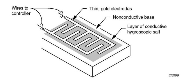
An older method that used resistance to determine relative humidity depended on a layer of hygroscopic salt, such as lithium chloride or carbon powder, deposited between two electrodes (Fig. 9). Both materials absorb and release moisture as a function of the relative humidity, causing a change in resistance of the sensor. An electronic controller connected to this sensor detects the changes in resistance, which it can use to provide control of relative humidity.
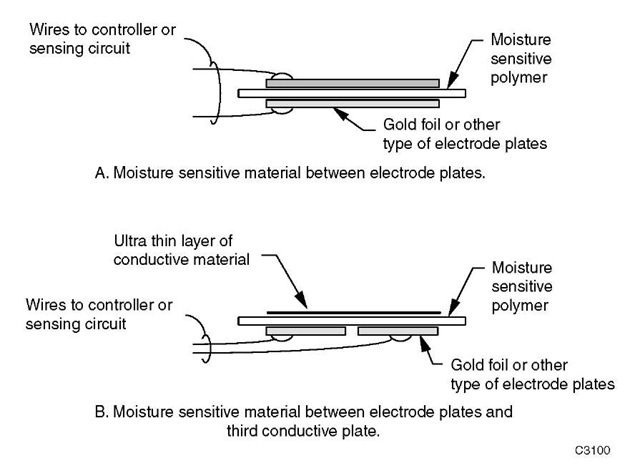
A method that uses changes in capacitance to determine relative humidity measures the capacitance between two conductive plates separated by a moisture-sensitive material such as polymer plastic (Fig. 10A). As the material absorbs water, the capacitance between the plates decreases, and the change can be detected by an electronic circuit. To overcome any hindrance of the material’s ability to absorb and release moisture, the two plates and their electric leadwires can be on one side of the polymer plastic, with a third sheet of extremely thin conductive material on the other side of the polymer plastic forming the capacitor (Fig. 10B). This third plate, too thin for attachment of leadwires, allows moisture to penetrate and be absorbed by the polymer, thus increasing sensitivity and response.
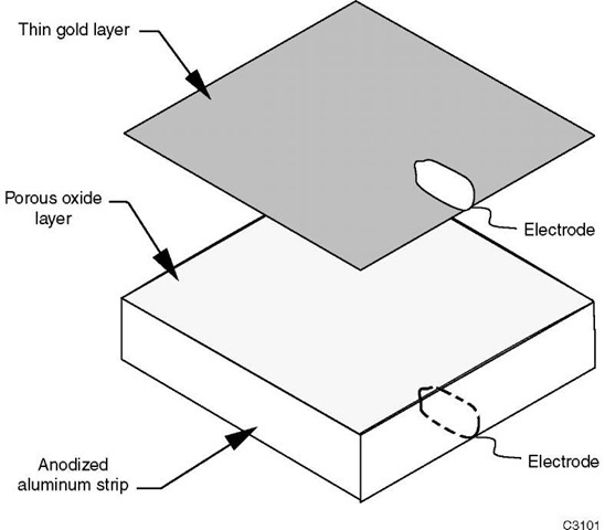
A relative humidity sensor that generates changes in both resistance and capacitance to measure moisture level is constructed by anodizing an aluminum strip and then applying a thin layer of gold or aluminum (Fig. 11). The anodized aluminum has a layer of porous oxide on its surface. Moisture can penetrate through the gold layer and fill the pores of the oxide coating, causing changes in both resistance and capacitance that can be measured by an electronic circuit.
Fig. 9 Resistive-type relative humidity sensor.
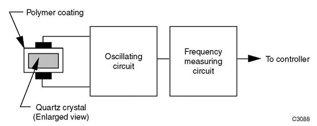
Sensors that use changes in frequency to measure relative humidity (Fig. 12) can use a quartz crystal coated with a hygroscopic material such as polymer plastic. When the quartz crystal is energized by an oscillating circuit, it generates a constant frequency. As the polymer material absorbs moisture and changes the mass of the quartz crystal, the frequency of oscillation varies and can be measured by an electronic circuit.
Most relative humidity sensors require electronics at the sensor to modify and amplify the weak signal and are referred to as transmitters. The electronic circuit compensates for the effects of temperature and both amplifies and linearizes the measured level of relative humidity. The transmitters typically provide a voltage or current output that can be used as an input to the electronic controller.
Pressure Sensors
An electronic pressure sensor converts pressure changes into a signal such as voltage, current or resistance that can be used by an electronic controller.
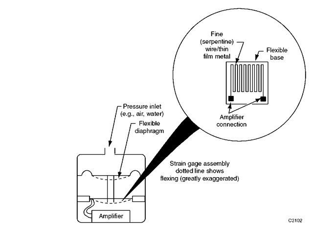
A method that measures pressure by detecting changes in resistance uses a small, flexible diaphragm and a strain gage assembly (Fig. 13). The strain gage assembly includes very fine (serpentine) wire or a thin metallic film deposited on a nonconductive base. The strain gage assembly is stretched or compressed as the diaphragm flexes with pressure variations. The stretching or compressing of the strain gage (shown by a dotted line in Fig. 13) changes the length of its fine wire or thin film metal, which changes the total resistance. The resistance can then be detected and amplified. These changes in resistance are small. Therefore, an amplifier is provided in the sensor assembly to amplify and condition the signal so the level sent to the controller is less susceptible to external noise interference. The sensor thus becomes a transmitter.
Fig. 10 Capacitance-type relative humidity sensor.
Fig. 11 Impedance-type relative humidity sensor.
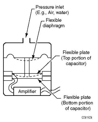
Another pressure sensing method measures capacitance (Fig. 14). A fixed plate forms one part of the capacitor assembly, and a flexible plate is the other part of the capacitor assembly. As the diaphragm flexes with pressure variations, the flexible plate of the capacitor assembly moves closer to the fixed plate (shown by a dotted line in Fig. 14) and changes the capacitance.
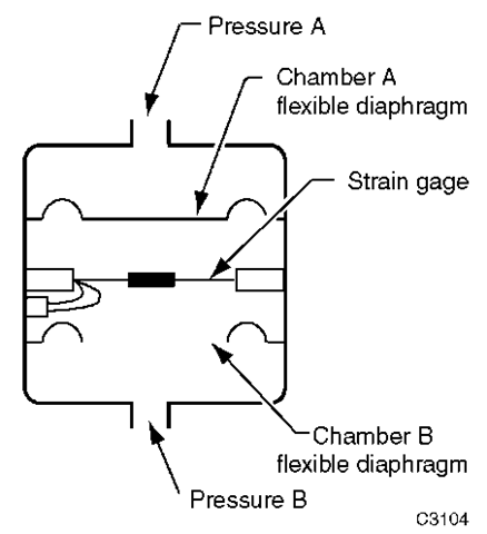
A variation of pressure sensors is one that measures differential pressure using dual pressure chambers (Fig. 15). The force from each chamber acts in an opposite direction with respect to the strain gage. This type of sensor can measure small differential pressure changes even with high static pressure.
Controllers, Output Devices and Indicating Devices
Controller
The electronic controller receives a sensor signal, amplifies and/or conditions it, compares it with the setpoint, and derives a correction if necessary. The output signal typically positions an actuator. Electronic controller circuits allow a wide variety of control functions and sequences, from very simple arrangements to multiple-input circuits with several sequential outputs. Controller circuits use solid-state components, such as transistors, diodes and integrated circuits, and include the power supply and all the adjustments required for proper control.
Fig. 12 Quartz crystal relative humidity sensor.
Fig. 13 Resistance-type pressure sensor.
Input Types
Electronic controllers are categorized by the type or types of inputs they accept, such as temperature, humidity, enthalpy or universal.
Temperature Controllers
Temperature controllers typically require a specific type or category of input sensors. Some have input circuits to
Fig. 14 Capacitance-type pressure transmitters.
accept RTD sensors such as BALCO or platinum elements, while others contain input circuits for thermistor sensors. These controllers have setpoint and throttling range scales labeled in degrees Fahrenheit or Celsius.
Relative Humidity Controllers
The input circuits for relative humidity controllers typically receive the sensed relative humidity signal already converted to a 0-10 V d.c. voltage, or a 4-20 mA current signal. Setpoint and scales for these controllers are in percent relative humidity.
Fig. 15 Differential pressure sensor.
Enthalpy Controllers
Enthalpy controllers are specialized devices that use specific sensors for inputs. In some cases, the sensor may combine temperature and humidity measurements and convert them to a single voltage to represent enthalpy of the sensed air. In other cases, individual dry-bulb temperature sensors and separate wet-bulb or relative humidity sensors provide inputs, and the controller calculates enthalpy. In typical applications, the enthalpy controller provides an output signal based on a comparison of two enthalpy measurements, indoor and outdoor, rather than on the actual enthalpy value. In other cases, the return air enthalpy is assumed constant so that only OA enthalpy is measured. It is compared against the assumed nominal return air value.
Universal Controllers
The input circuits of universal controllers can accept one or more of the standard transmitter or transducer signals. The most common input ranges are 0-10 V d.c. and 4-20 mA. Other input variations in this category include a 2-10 V d.c. and a 0-20 mA signal. Because these inputs can represent a variety of sensed variables, such as a current of 0-15 A or pressure of 0-3000 psi, the settings and scales are often expressed in percent of full scale only.
Control Modes
The control modes of some electronic controllers can be selected to suit the application requirements. Control modes include two-position, proportional and proportional-integral. Other control features include remote setpoint, the addition of a compensation sensor for reset capability, and override or limit control.
Output Control
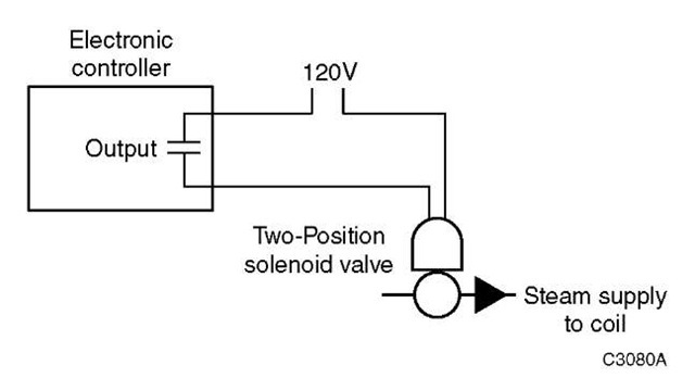
Electronic controllers provide outputs to a relay or actuator for the final control element. The output is not dependent on the input types or control method. The simplest form of output is two-position, in which the final control element can be in one of two states. For example, an exhaust fan in a mechanical room can be turned either on or off. The most common output form, however, provides a modulating output signal which can adjust the final control device (actuator) between 0 and 100 %, such as in the control of a chilled water valve.
Fig. 16 Two-position control.
Output Devices
Actuators, relays, and transducers (Fig. 2) are output devices which use the controller output signal (voltage, current, or relay contact) to perform a physical function on the final control element such as starting a fan or modulating a valve. Actuators can be categorized as devices that provide two-position action or as those that provide modulating action.
Two-Position
Two-position devices such as relays, motor starters, and solenoid valves have only two discrete states. These devices interface between the controller and the final control element. For example, when a solenoid valve is energized, it allows steam to enter a coil that heats a room (Fig. 16). The solenoid valve provides the final action on the controlled media, steam. Damper actuators can also be designed to be two-position devices.
Modulating
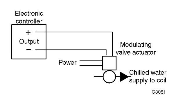
Modulating actuators use a varying control signal to adjust the final control element. For example, a modulating valve controls the amount of chilled water entering a coil so that cool supply air is just sufficient to match the load at a desired setpoint (Fig. 17). The most common modulating actuators accept a varying voltage input of 0-10 V, or 2-10 V d.c., or a current input of 4-20 mA. Another form of actuator requires a pulsating (intermittent) or duty cycling signal to perform modulating functions. One form of pulsating signal is a Pulse Width Modulation (PWM) signal.
Fig. 17 Modulating control.
Fig. 18 Electric-to-pneumatic transducer.
Tranducer
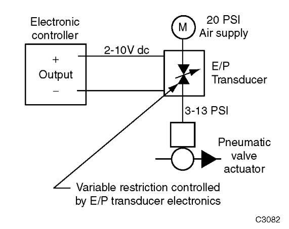
In some applications, a transducer converts a controller output to a signal that is usable by the actuator. For example, Fig. 18 shows an Electronic-to-Pneumatic (E/P) transducer that converts a modulating 2-10 V d.c. signal from the electronic controller to a pneumatic proportional modulating 3-13 psi signal for a pneumatic actuator.
Indicating Devices
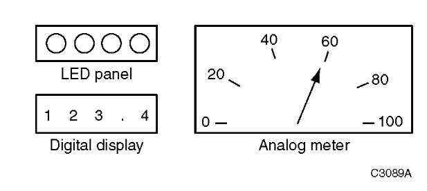
An electronic control system can be enhanced with visual displays that show system status and operation. Many electronic controllers have built-in indicators that show power, input signal, deviation signal and output signal. Fig. 19 shows some types of visual displays. An indicator light can show on/off status or, if driven by controller circuits, the brightness of a light can show the relative strength of a signal. If a system requires an analog or digital indicating device and the electronic controller does not include this type of display, separate indicating devices can be provided.
Interface with Other Systems
It is often necessary to interface an electronic control device to a microprocessor-based building management system or other related system. An example is an interface that allows a building management system to adjust the setpoint or amount of reset (compensation) for a specific controller. Compatibility of the two systems must be verified before they are interconnected.
Fig. 19 Indicating devices.
ELECTRONIC CONTROLLER FUNDAMENTALS
General
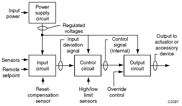
The electronic controller is the basis for an electronic control system. Fig. 20 shows the basic circuits of an electronic controller including power supply, input, control and output. For greater stability and control, internal feedback correction circuits also can be included, but these are not discussed here. The circuits described provide an overview of the types and methods of electronic controllers.
Power Supply Circuit
The power supply circuit of an electronic controller provides the required voltages to the input, control, and output circuits. Most voltages are regulated DC voltages. The controller design dictates the voltages and current levels required.
All power supply circuits are designed to optimize both line and load regulation requirements within the needs and constraints of the system. Load regulation refers to the ability of the power supply to maintain the voltage output at a constant value even as the current demand (load) changes. Similarly, line regulation refers to the ability of the power supply to maintain the output load voltage at a constant value when the input (AC) power varies. The line regulation abilities or limitations of a controller are usually part of the controller specifications such as 120 V AC + 10%, -15%. The degree of load regulation involves the end-to-end accuracy and repeatability, and is usually not explicitly stated as a specification for controllers.
TYPICAL SYSTEM APPLICATIONS
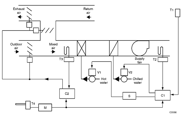
Fig. 21 shows a typical air-handling system controlled by two electronic controllers, C1 and C2; sequencer S; multi-compensator M; temperature sensors T1 through T4; modulating hot- and chilled-water valves V1 and V2; and outdoor, return, and exhaust air damper actuators. The control sequence is as follows:
• Controller C1 provides outdoor compensated, summer/ winter control of space temperature for a heating/ cooling system which requires PI control with a low limit. Sensor T4 provides the compensation signal through multi-compensator M, which allows one outdoor temperature sensor to provide a common input to several controllers. Controller C1 modulates the hot-and chilled-water valves V1 and V2 in sequence to maintain space temperature measured by sensor T1 at a pre-selected setpoint. Sequencer S allows sequencing the two valve actuators from a single controller. Low-limit sensor T2 assumes control when the discharge air temperature drops to the control range of the low-limit setpoint. A minimum discharge air temperature is maintained regardless of space temperature.
Fig. 20 Electronic controller circuits.
When the outdoor temperature is below the selected reset changeover point set on C1, the controller is in the winter compensation mode. As the outdoor air temperature falls, the space temperature setpoint is raised. When the outdoor temperature is above the reset changeover point, the controller is in the summer compensation mode. As the outdoor temperature rises, the space temperature setpoint is raised.
• Controller C2 provides PI mixed air temperature control with economizer operation. When the OA temperature measured by sensor T4 is below the setting of the economizer startpoint setting, the controller provides proportional control of the dampers to maintain mixed air temperature measured by sensor T3 at the selected setpoint. When the OA temperature is above the economizer startpoint setting, the controller closes the OA dampers to a preset minimum.
Fig. 21 Typical application with electronic controllers.
ADDITIONAL DEFINITIONS
Authority (reset authority or compensation authority). A setting that indicates the relative effect a compensation sensor input has on the main setpoint (expressed in percent).
Compensation change-over. The point at which the compensation effect is reversed in action and changes from summer to winter or vice versa. The percent of compensation effect (authority) may also be changed at the same time.
Control Point. The actual value of a controlled variable (setpoint plus or minus offset).
Deviation. The difference between the setpoint and the value of the controlled variable at any moment. Also called “offset.”
Direct acting. A direct-acting controller increases its output signal on an increase in input signal.
Electric control. A control circuit that operates on line or low voltage, and uses a mechanical means, such as a temperature-sensitive bimetal or bellows, to perform control functions, such as actuating a switch or positioning a potentiometer. The controller signal usually operates or positions an electric actuator, although relays and switches are often controlled.
Electronic control. A control circuit that operates on low voltage and uses solid-state components to amplify input signals and perform control functions, such as operating a relay or providing an output signal to position an actuator. Electronic devices are primarily used as sensors. The controller usually furnishes fixed control routines based on the logic of the solid-state components.
Electronic controller. A solid-state device usually consisting of a power supply, a sensor amplification circuit, a process/comparing circuit, an output driver section, and various components that sense changes in the controlled variable and derive a control output which provides a specific control function. In general, adjustments such as setpoint and throttling range necessary for the process can be done at the controller via potentiometers and/or switches.
Final control element. A device such as a valve or damper that changes the value of the manipulated variable. The final control element is positioned by an actuator.
Integral action (I). An action in which there is a continuous linear relationship between the amount of increase (or decrease) on the output to the final control element and the deviation of the controlled variable to reduce or eliminate the deviation or offset.
Limit sensor. A device which senses a variable that may be other than the controlled variable and overrides the main sensor at a preset limit.
Main sensor. A device or component that measures the variable to be controlled.
Negative (reverse) reset. A compensating action in which a decrease in the compensation variable has the same effect as an increase in the controlled variable. For example, in a heating application, as the outdoor air temperature decreases, the control point of the controlled variable increases. Also called “winter reset or compensation.”
Offset. A sustained deviation between the control point and the setpoint of a proportional control system under stable operating conditions. Also called “deviation.”
Positive (direct) reset. A compensating action in which an increase in the compensation variable has the same effect as an increase in the controlled variable. For example, in a cooling application, as the OA temperature increases, the control point of the controlled variable increases. Also called “summer reset or compensation.”
Proportional band (throttling range). In a proportional controller, the control point range through which the controlled variable must pass to drive the final control element through its full operating range. Proportional band is expressed in percent of the main sensor span. A commonly used equivalent is “throttling range,” which is expressed in values of the controlled variable.
Proportional control (P). A control algorithm or method in which the final control element moves to a position proportional to the deviation of the value of the controlled variable from the setpoint.
Proportional-integral (PI) control. A control algorithm that combines the proportional (proportional response) and integral or deviation control algorithms. Integral action tends to correct the offset resulting from proportional control. Also called “proportional plus reset” or “two-mode” control.
Remote setpoint. A means for adjusting the controller setpoint from a remote location, in lieu of adjusting it at the controller itself. The means of adjustment may be manual with a panel or space mounted potentiometer, or automatic when a separate device provides a signal (voltage or resistive) to the controller.
Reset control. A process of automatically adjusting the control point of a given controller to compensate for changes in a second measured variable such as outdoor air temperature. For example, the hot deck control point is reset upward as the outdoor air temperature decreases. Also known as “compensation control.”
Reset sensor. The system element which senses a variable other than the controlled variable and resets the main sensor control point. The amount of this effect is established by the authority setting.
Reverse acting. A reverse-acting controller decreases its output signal on an increase in input signal.
Setpoint. The value on the controller scale at which the controller is set, such as the desired room temperature set on a thermostat. The setpoint is always referenced to the main sensor (not the reset sensor).
Throttling range. In a proportional controller, the control point range through which the controlled variable must pass to move the final control element through its full operating range. Throttling range is expressed in values of the controlled variable such as temperature in degrees Fahrenheit, relative humidity in percent, or pressure in pounds per square inch. A commonly used equivalent is “proportional band,” which is expressed in percent of sensor span for electronic controls.
Transducer. A device that converts one energy form to another. It amplifies (or reduces) a signal so that the output of a sensor or transducer is usable as an input to a controller or actuator. A transducer can convert a pneumatic signal to an electric signal (P/E transducer) or vice versa (E/P transducer), or it can convert a change in capacitance to an electrical signal.
Transmitter. A device that converts a sensor signal to an input signal usable by a controller or display device.
CONCLUSION
Basic automatic electronic control systems are extremely important to provide desirable operational features of energy-using equipment and systems. Proper control is critical to achieving functional performance, as well as energy-efficient performance in equipment, buildings and processes.
