Abstract
Asymmetric operation of an electric power transmission corridor is an operating strategy that enables a 3-phase line to be operated with one or two phases out of service in the case of single-line transmission corridors, or with one, two, or three phases out of service in the case of multiple-line corridors, while preserving 3-phase symmetrical operation at corridor extremities. This article shows how asymmetric operation is implemented, how much it costs, and how it can improve the reliability and economics of electric power transmission systems.
INTRODUCTION
Existing electric power transmission systems are operated with three physically different systems of conductors referred to as “phases,” where the sinusoidal voltages and currents in each phase are offset with respect to one another to take advantage of Nicolas Tesla’s groundbreaking invention of the 3-phase alternating-current (AC) generator and motor. The 3-phase power generator is a remarkably robust and economical technology that creates the three sets of voltages and currents, the so-called phases, in 3-phase transmission lines. This results in a steady torque characteristic, which in turn translates into high generator reliability. The 3-phase AC motor, which requires an infeed of the three different phases to operate, is also a highly reliable and economic piece of machinery, and is a workhorse of industry.
Because 3-phase generators and motors are so widely used, they are connected to 3-phase high-voltage (HV), extra-high-voltage (EHV), or ultra-high-voltage (UHV) power transmission systems that are symmetrically operated, meaning that if any problem develops on one or more phases, all three phases are taken out of service. This requirement is due to the fact that if symmetric operation is not enforced, undesirable voltages and currents are generated that are harmful not only to rotating machinery, but also to many other types of loads. There are exceptions to this rule: For economical reasons, single-phase systems equipped with appropriate mitigating measures have been used in railway electrification and for distributing power at the household level. Throughout the world, however, standard practice is to operate bulk 3-phase power transmission systems symmetrically.
Symmetric Operation of Power Transmission Systems
When at least one phase of a power transmission line touches an object, causing the current of that phase to be redirected either to the ground (i.e., through a tree) or to another phase, such short-circuit conditions are generally referred to as “faults.” Under normal operation, when a fault condition occurs, circuit breakers at both ends of the line interrupt the current in all three phases, effectively removing the line from operation until such time as the fault condition has been removed, even though one or two healthy phases remain that conceivably could carry useful power. Such a strategy has several disadvantages. First, a problem on 33% of a line automatically deprives the network of 100% of this same line. Second, the operation of three phases as a single organic whole rather than three independent conductors augments the probability of loss of 3-phase transmission by nearly a factor of three with respect to single-phase transmission. Finally, after a fault is cleared, the power system operator must apply remedial measures, such as changing the amount of generation from different power plants, to redirect power flows and ensure that the system is capable of sustaining further contingencies with no impact on load power delivery. This exposes power system operation to the possibility of human error and, therefore, increases operating risks.
Though such a conservative operating strategy served the industry well while it was economically possible to do so, it would seem that the electric power industry’s prevalent transmission strategy today is wasteful of expensive transmission equipment, costly in terms of loss of potential revenue, and stressful to both power system equipment and operators. In the light of the considerable pressures on electric utilities due to deregulation, greater environmental awareness, normal load growth, and (as shown later in this article) symmetrical operation expose the system to numerous risks while wasting valuable transmission capacity. This was particularly shown to be true in the August 2003 blackout in the northeastern United States, and Canada in which many lines were switched out due to single-phase faults.[1]
Electric Power Transmission Systems: Asymmetric Operation
Asymmetric Operation of Power Transmission Systems
Asymmetric operation is essentially defined as the operation of a 3-phase transmission line as three independently operated entities.[2] In this approach, a 3-phase line can be operated with one or two phases out of service for single-line transmission corridors, or with one, two, or even three phases out of service in the case of multiple-line corridors. For this to occur, the strategy implements three operational objectives:
1. Upon entering asymmetric operation, undesirable voltages and currents are “contained” within the affected corridor.
2. From the system perspective, the corridor appears to operate symmetrically at both extremities.
3. From the system perspective, the faulted corridor returns to its precontingency electrical state (i.e., in terms of impedance, voltages, and currents) and maintains precontingency power flows.
Because the post-contingency system is electrically indistinguishable from its precontingency state, this eliminates the need for operator-driven postfault remedial measures. Postfault remedial measures are, therefore, built into the strategy.
To enable asymmetric operation as described above, compensating equipment must be introduced into the corridor just as the faulted phase(s) is(are) switched out by means of circuit breaker action. Such compensating equipment can either be conventional, inexpensive passive devices, such as capacitors and reactors equipped with appropriate switching equipment, or more complex and expensive power-electronic devices such as Flexible AC Transmission System (FACTS) controllers. Both approaches have their strengths and weaknesses, and the final choice will often depend on system-specific constraints imposed by the system planner.
The consequence of asymmetric operation is to add flexibility to transmission system operation, increase corridor reliability, and increase security limits (i.e., the amount of power transferred under normal conditions) and thereby improve transmission economics.
BENEFIT OF ASYMMETRIC OPERATION
Statistics of Transmission Line Failures
Most transmission line faults are single-phase faults (varying from 60 to 97% with increasing voltage level).[3'4] This alone is sufficient motivation for studying asymmetric operation, even if the practice of single pole reclosure is successful up to 50% of the time at voltages up to 765 kV. Because it is so simple to define and to employ, the 3-phase fault—often used concurrently with the subsequent loss of major transmission equipment—has long been the industry norm for estimating system performance under difficult conditions. Even so, one must occasionally be reminded of the fact that 3-phase faults have no more than a 1% probability of occurrence and that their use as a criterion is clearly limited in terms of physical significance. Indeed, given such a statistic, one could argue that a symmetrical 3-phase response to normally occurring events and contingencies is an inappropriate response 99% of the time and, therefore, is far from optimal from an operations perspective.
In the past, this criterion served a useful purpose as an umbrella contingency, covering a large number of contingencies and accounting for lack of knowledge of either a specific operating context or of power system dynamics more generally. Asymmetric operation, however, enables power systems to respond surgically to contingencies while subsuming symmetrical response capability when required.
Reliability Analysis
The most frequently used reliability index in transmission planning is the loss of load expectation (LOLE), which is the expected mean of energy not supplied due to the failure of network components.1-5-1 Here, the LOLE is used for estimating and comparing the risk of operating a single- or multiple-line transmission corridor under symmetric or asymmetric operation.
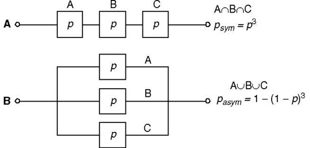
Fig. 1 shows the logic circuits for the reliability analysis of a 3-phase transmission line under symmetrical or asymmetrical operation. In the symmetrical approach, events leading to the loss of any phase results in the loss of all three phases; in this case, the equivalent logical circuit presents the three phases in series. In the asymmetrical approach, the three phases function independently; thus, the equivalent logical circuit presents the three phases in parallel.
If one considers a corridor of N 3-phase lines transmitting a total power value of T, where the probability of successful transmission of each phase of each 3-phase line is p, the expected mean nontransmitted power according to symmetric operation LOLEsym and the expected mean nontransmitted power according to asymmetric operation LOLEasym are[2]
Fig. 1 Equivalent logical circuits of a 3-phase line under (A) symmetric operation and (B) asymmetric operation.
where fch is a load factor that takes average load variations into account. An arbitrary load factor between 50 and 75% is considered to be acceptable in the industry.
The difference between the LOLE of symmetric and asymmetric operation, ALOLE, yields the benefit of asymmetric operation, which can be evaluated at the energy generation cost
Eq. 2 shows that ALOLE is always greater than zero (ALOLE> 0) for 0<p < 1. This means that if the probability of successful transmission of the energy from the sending end to the receiving end is the same for all phases, the risk of nontransmission is always higher in the case of symmetric operation.
Example 1 Asymmetric Operation of a 2-Line, 400 kV, 300 km Corridor
The probability of nontransmission can be evaluated as 0.133% per 100 km of line.[6] Thus, for each phase with an equivalent length of 300 km, one has: q = 1 — p = 0.004 and p = 0.996. The benefit of asymmetric operation is obtained from Eq. 2 as ALOLE = 0.01195/ch T. Assuming a generation cost of 2500 $/kW and a load factor of 75%, the benefit of the asymmetric approach over the symmetric approach is approximately 23 $/kW.
IMPLEMENTATION
Two distinct cases must be addressed for the purpose of implementing asymmetric operation: (1) the multiple-line corridor and (2) the single-line corridor. As previously pointed out, either of two implementation strategies can be employed: (1) conventional devices (i.e., passive LC elements with electromechanical switches or circuit breakers) or (2)power-electronic devices.[7] Though the latter incorporate significant advantages, including rapid response and precise control, the following sections focus on the use of conventional devices due to their lower cost.
Multiple-Line Corridor
A lossless, uncoupled, lumped-parameter transmission line model is used as a starting point for quantifying the compensation strategy; this simplifies the analysis and focuses on the underlying concepts while leading to a reasonable estimate of the capacity and cost of the required compensating equipment. Though more complex distributed parameter line models enable such factors as line resistance to be thoroughly accounted for, the results presented in the following sections are remarkably precise because line resistance is typically very low.[2]
Compensating Impedances
The design of the compensation strategy begins by considering a corridor of N parallel lines (N = 2). The corridor, therefore, includes N instances of each phase, where at, bt, and ct, respectively, refer to the A, B, and C phases of the ith line. Let us consider the case with L of the individual at-phases out of service. The problem is to determine the conditions for which the power transmitted on all of the N individual at-phases in symmetric mode is equal to that of N—L compensated remaining at-phases in asymmetric mode and then deduce the values of the compensating impedances.
Fig. 2A shows the equivalent circuit of the N parallel ar phases working in symmetric mode, all individual phases being in service. Vs and VR are, respectively, the line-to-line rms voltages of the sending and the receiving ends of the transmission system, and Xp and Bp are, respectively, the series impedance and the shunt suscep-tance of each at-phase.
With L of the at-phases out of service due to faults, the equivalent circuit of the N—L remaining sound at-phases in parallel in asymmetric mode is shown in Fig. 2B. and Bc are, respectively, the series impedance and the shunt susceptance of the compensating devices for each at-phase, defined as follows:
With these compensating elements, the asymmetrically operated compensated corridor A-phase with L of
Fig. 2 Equivalent circuit of one phase of a corridor in symmetric and asymmetric operation: (A) corridor A-phase in symmetric operation, consisting of N individual arphases; (B) corridor A-phase in asymmetric operation, consisting of N—L individual arphases.
Fig. 2 Equivalent circuit of one phase of a corridor in symmetric and asymmetric operation: (A) corridor A-phase in symmetric operation, consisting of N individual arphases; (B) corridor A-phase in asymmetric operation, consisting of N—L individual arphases.
the Aj-phases out of service has the same electrical characteristics and carries the same power as the original symmetrically operated corridor A-phase with N operational at-phases.
Installed Reactive Power
The total installed reactive power for series compensation QTseries is calculated assuming that series-connected reactive power is available to every phase of every line. The total installed series reactive power in the 3N phases of the corridor is
where Ip is the rms value of the current in the equivalent line, is the impedance of the series compensating device, and Xp is the series impedance of each at-phase.
The value of the total installed shunt reactive power QTshunt is again calculated based on the fact that any phase of any line can be lost. There is no need to compensate for any particular at-phase, however, as shunt compensation can be installed on the sending-end and receiving-end buses. Consequently, the total reactive power installed for shunt compensation is given by:
where Bc is the shunt susceptance of the compensating devices for each at-phase; Bp is the shunt susceptance of each at-phase; and VN is the rms phase-to-ground voltage, assumed to be the same at the two ends of the corridor.
where Bc is the shunt susceptance of the compensating devices for each at-phase; Bp is the shunt susceptance of each at-phase; and VN is the rms phase-to-ground voltage, assumed to be the same at the two ends of the corridor.
Example 2 Two-Line, 400 kV, 300 km Corridor with Lossless Lines (Fig. 3)
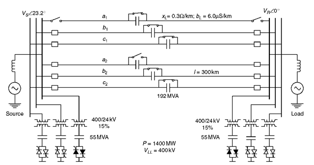
In this example, the methodology is applied for the particular case of two 400 kV, 300 km, lossless, transposed lines loaded to their surge impedance loading
Fig. 3 Compensation scheme for asymmetric operation of a 2-line, 400 kV, 300 km corridor (assuming a lossless conductor model).
(SIL= 1400 MW) and equipped to sustain the loss of three different phases on either of the two 3-phase lines. Fig. 3 shows this corridor with one phase out of service on one line. The unit length parameters are xL = 0.3 fi/km and
= 6.0 nS/km. Thus, for 300 km, XL = 90 fi, and BL = 1.80X 10″3 S.
For L = 1, Table 1 gives the required reactive power resulting from the application of Eqs. 4 and 5. For series compensation, a total 1150 Mvar is required. The total need for shunt compensation, including 15% reactive impedance representing Static Var System (SVS) transformer losses, is 330 Mvar.
Remarks
The case developed above for N lines with L of the at, bt, or ct phase out of service is theoretical. Indeed, the case of L > 1 has such a low probability of occurrence that it is questionable whether such a contingency need ever be considered. Additionally, as L goes from 1 to 2, compensation requirements and operational complexity are far greater, as one must provide suitable reactive power sources and associated switching for all values of L.
For these reasons, it seems practical to design for the loss of only one at-, bt-, or ct-phase. Even so, the case of L = 1 covers the loss of 1 at-phase, 1 bt-phase, or 1 ct-phase for any combination of lines, or all three phases of a single line. In the case of a 2-line corridor, the maximum corridor power transfer will be maintained after sustaining up to three single-phase contingencies for any combination of phases on the two different lines. After having sustained a third contingency, however, power transfer would normally be reduced for security considerations. As can be seen, this goes beyond the 3-phase N — 1 criterion traditionally used to establish security limits, where N is the number of 3-phase lines in a corridor. Asymmetric operation thus maintains full corridor capacity under challenging circumstances while providing the system operator the precious time required to restore it to its precontingency physical state.
Single-Line Corridor
The solution proposed for the single-line case is based on the application of symmetrical components to balance the resulting 2-phase or 1-phase transmission after the loss of one or two phases, respectively. The currents of the negative and zero sequences resulting from a 1-phase-open or 2-phase-open situation are not negligible and must be filtered or compensated so as to guarantee an adequate asymmetric operation. As the single-phase fault has the highest probability of occurrence, the loss of two phases is not considered here.
Table 1 Total reactive power requirements for the asymmetric operation of a 2-line, 400 kV, 300 km corridor equipped to sustain the loss of any three phases in the corridor (assuming a lossless conductor model)
| Total transmitted power P = 1400 MW | |
| Reactive power Q (Mvar) | |
| Series compensation | 1150 Mvar |
| Shunt compensation | 330 Mvar |
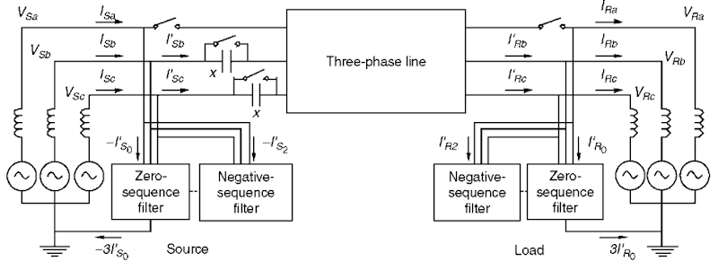
Fig. 4 shows the principle of asymmetric operation of a 3-phase line with phase a out of service. In normal symmetric operation, the two connected networks and the line are perfectly balanced. During asymmetric operation with one phase open, three basic compensating elements must be introduced to rebalance the voltages and currents:
1. Series compensation of the sound phases (phases b and c in Fig. 4) to lower the series reactance, maintain the same angular spread, and thus ensure the flow of the precontingency power transfer. Series compensation can be supplied by means of either conventional capacitors or series-controlled voltage sources employing power-electronic devices. The compensating elements can be placed at the sending end, the receiving end, or the center of the line.
2. Zero-sequence filters, at each end of the line, to afford a low-impedance path for the zero sequence current. Many designs can be used to implement such filters:
• a single T, zigzag, or A – Y transformer
• combinations of passive LC elements that may be variable to reflect large load variations
• controlled shunt current sources made up of power-electronic devices.
3. Negative sequence compensators at each end of the line to eliminate the negative-sequence current by injecting an opposite current of the same magnitude. Here again, the negative sequence compensators can be constructed of passive LC elements connected in delta or star, or of controlled shunt current sources employing power electronic converters. Depending on the planning criteria, the negative-sequence compensator and zero-sequence filter at each end of the line can be grouped together.[2]
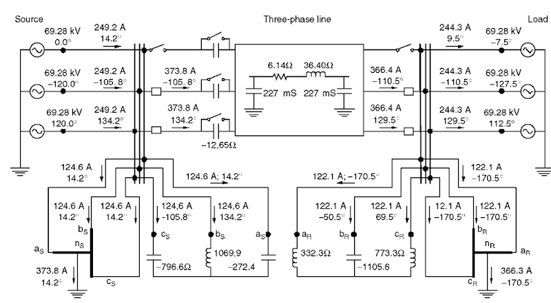
Example 3 Asymmetric Operation of a Single-Line, 120 kV, 100 km Corridor (Fig. 5)
show the calculation results and the reactive power needed for asymmetric operation of the line with a phase open. Compensation of the positive sequence requires three capacitors of 2 Mvar each for a total 6 Mvar. The compensation of the negative sequence requires 68 Mvar for the two compensators at the ends of the line. Filtering the zero sequence requires 16 Mvar.
Fig. 4 Concept of asymmetric operation of a single-line corridor.
Remarks
The values of the passive LC elements of the negative-sequence compensator depend on the actual load, and it may be necessary to adjust them for large variations of the load from SIL (design load). Adjusting the grounding transformers of the zero-sequence filters according to the actual load is not necessary because impedances are designed for maximum load conditions.
In a sense, this solution is an extension of the principle of load compensation.1-8-1 As pointed out earlier, FACTS controller-based implementations can provide better and more rapid control but cost more than conventional solutions.
FINANCIAL ANALYSIS
The LOLE can also be expressed as the loss of revenue related to the energy not delivered in 1 year; such a figure can then be used to determine how long it takes to pay for the equipment required to implement either asymmetric operation or some other alternative, such as adding another line. The purpose of this section is to show that asymmetric operation is a practical and economical alternative for improving transmission system capacity.
Fig. 5 Asymmetric operation of a single-line, 120 kV, 100 km corridor with one phase open (assuming the use of conventional compensating devices).
Table 2 Calculated results of the operation of a single-line, 120 kV, 100 km corridor with one phase open, using conventional compensating devices
Retrofit of Existing Corridors
The benefit of asymmetric operation is obtained by comparing (1) the total investment cost of retrofitting an existing 3-phase corridor for asymmetric operation and (2) the LOLE of 3-phase symmetrical operation— expressed in dollars—which is offset by means of asymmetric operation. Initially, the annual savings generated by asymmetric operation can be used to reimburse the equipment investment; after this investment has been repaid, this represents additional revenue to the utility. Table 3 summarizes the financial analysis for three 400 kV, 150 km asymmetrically operated corridors involving, respectively, one, two, and three transmission lines. For purposes of comparison, one also finds both the cost of a new line on this table and the cost of implementing a typical FACTS-based compensation strategy.[2]
For the single-line case, the cost of the LOLE is lower than the investment cost of asymmetric operation (and
much lower than the cost of building a new line). The payback period, therefore, is greater than 1 year. The cost of LOLE for this case, however, does not take into account the larger social and economic costs associated with the total loss of the power supply in the symmetric operation mode, which are not addressed here.
For two or three lines, the investment cost of asymmetric operation using conventional devices is lower than the cost of the LOLE: in this case, the payback time of asymmetric operation is less than 1 year.
In a general way, one sees that the cost of implementing asymmetric operation by retrofitting multiple lines is always lower than in the single-line case because one exploits the transmission equipment already in place. In other words, part of the equipment required to implement asymmetric operation is already there!
As a final note, all three cases provide remarkable performance in relation to the standard 3-phase N — 1 security criterion.[9] Case 1, when operated asymmetrically, respects the single-phase N — 1 criterion, whereas symmetrical operation of this same line is incapable of respecting any N — 1 criterion, either 1-phase or 3-phase. Cases 2 and 3, when operated asymmetrically, are capable of respecting the full 3-phase N — 1 criterion in addition to a single-phase N — 1 criterion. All this translates into high transmission reliability and improved transmission economics.
Table 3 Comparing the cost of three options at 400 kV for reducing the risk of nontransmitted energy (costs are expressed in millions of dollars Canadian)
| Case 1 | Case 2 | Case 3 | |
| Number of lines | 1 | 2 | 3 |
| Voltage (kV) | 400 | 400 | 400 |
| Line length (km) | 150 | 150 | 150 |
| Transmitted power (MW) | 700 | 1400 | 2000 |
| Probability of failure of one phase[6] | 0.002 | 0.002 | 0.002 |
| Load factor (%) | 75 | 75 | 75 |
| Cost of power not supplied: LOLE (M$CA) Asymmetric operation with conventional devices | 8 | 16 | 23 |
| Investment Cost (M$CA) | 48 | 15.0 | 12.1 |
| Payback time (years) | 6.0 | 0.93 | 0.53 |
| Asymmetric operation with FACTS devices | |||
| Investment cost (M$CA) | 70 | 42.8 | 34.7 |
| Payback time (years) | 8.8 | 2.7 | 1.5 |
| New line | |||
| Investment cost (M$CA) | 60 | 60 | 60 |
| Payback time (years) | 7.5 | 3.8 | 2.6 |
New Corridors
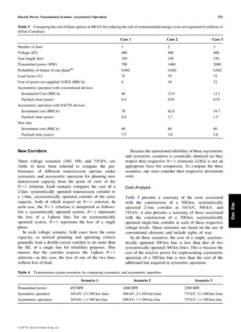
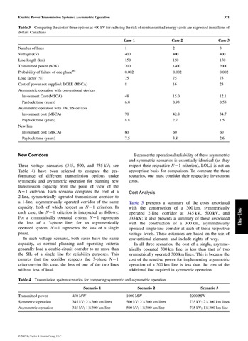
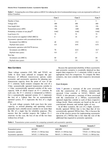
Three voltage scenarios (345, 500, and 735 kV; see Table 4) have been selected to compare the performance of different transmission options under symmetric and asymmetric operation for planning new transmission capacity from the point of view of the N — 1 criterion. Each scenario compares the cost of a 2-line, symmetrically operated transmission corridor to a 1-line, asymmetrically operated corridor of the same capacity, both of which respect an N — 1 criterion. In each case, the N — 1 criterion is interpreted as follows: For a symmetrically operated system, N — 1 represents the loss of a 3-phase line; for an asymmetrically operated system, N — 1 represents the loss of a single phase.
In each voltage scenario, both cases have the same capacity, as normal planning and operating criteria generally load a double-circuit corridor to no more than the SIL of a single line for reliability purposes. This ensures that the corridor respects the 3-phase N — 1 criterion—in this case, the loss of one of the two lines without loss of load.
Because the operational reliability of these asymmetric and symmetric scenarios is essentially identical (as they respect their respective N — 1 criterion), LOLE is not an appropriate basis for comparison. To compare the three scenarios, one must consider their respective investment costs.
Cost Analysis
Table 5 presents a summary of the costs associated with the construction of a 300 km, symmetrically operated 2-line corridor at 345 kV, 500 kV, and 735 kV; it also presents a summary of those associated with the construction of a 300 km, asymmetrically operated single-line corridor at each of these respective voltage levels. These estimates are based on the use of conventional elements and include rights of way.
In all three scenarios, the cost of a single, asymmetrically operated 300 km line is less than that of two symmetrically operated 300 km lines. This is because the cost of the reactive power for implementing asymmetric operation of a 300 km line is less than the cost of the additional line required in symmetric operation.
Table 4 Transmission system scenarios for comparing symmetric and asymmetric operation
| Scenario 1 | Scenario 2 | Scenario 3 | |
| Transmitted power | 450 MW | 1000 MW | 2200 MW |
| Symmetric operation | 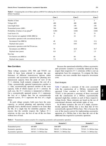 |
 |
 |
| Asymmetric operation | 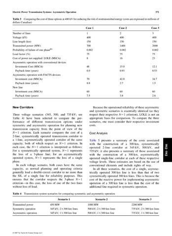 |
 |
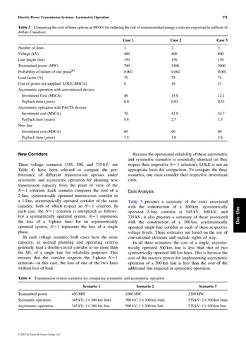 |
Table 5 Costs associated with symmetric and asymmetric operation for the three scenarios of Table 4 (costs are expressed in millions of dollars Canadian)
Effect of Line Length
In the above example, line length was set somewhat arbitrarily at 300 km even though all scenarios are technically realistic. There is considerable merit, however, in comparing the costs of a 1-line, asymmetrically operated corridor as a function of distance with respect to those of a 2-line symmetrically-operated corridor. This was examined, therefore, in the case of the three voltage scenarios considered above and for line lengths ranging from 1 to 400 km.
As Fig. 6 shows, the costs of both symmetric and asymmetric operation vary linearly with line length but at different rates. For short lines, the cost of asymmetric operation is higher because the cost of shunt compensation is predominant. For long lines, the cost of symmetric operation is higher because the cost of the lines increases more quickly than the cost of compensation. As shown, there exists a point for each scenario at which, between 100 and 200 km, an asymmetrically operated 1-line corridor costs less to build than a symmetrically operated
2-line corridor of the same voltage. Such cost behavior is similar to that found in comparisons of AC and DC transmission corridors, where, beyond a certain point, DC transmission is less costly than the equivalent AC solution.
CONCLUSION
Asymmetric operation transforms power system planning and operation by virtue of the greater flexibility available in finding solutions to specific challenges. Though actual implementations will generally require detailed simulation and engineering of components and systems for such purposes as insulation coordination, protection, control, security, and reliability, the numerous examples presented here show that the concepts are applicable to any voltage level.
In the case of multiple-line corridors, it has been shown that conversion to asymmetric operation increases the corridor availability, reduces the loss of load expectation, and increases the secure power transfer limit (as each and every line can be operated at its SIL) while respecting existing 3-phase N — 1 security criteria if need be. In the case of new transmission corridors, point-to-point transmission, interarea network interconnections, or ring-type transmission grids feeding large metropolitan areas, asymmetric operation has such a positive impact on the reliability of single-line transmission systems that it redefines one’s outlook on such fundamental issues as choice of voltage, number of lines, the contingency that defines one’s security criterion, the amount of power transferred securely, and the amount of land required for transmission rights of way. In short, asymmetric operation redefines the reliability, environmental impact, and economics of the planning and operation of AC power transmission.
Fig. 6 Cost comparison of symmetric (S.O.) and asymmetric (A.O.) operation for three scenarios as a function of line length (costs are expressed in millions of dollars Canadian).
![tmp50-2[3] tmp50-2[3]](http://lh3.ggpht.com/_1wtadqGaaPs/TGoweSa_P9I/AAAAAAAAPyE/E5NV14WYoyo/tmp5023_thumb.jpg?imgmax=800)
![tmp50-3[3] tmp50-3[3]](http://lh4.ggpht.com/_1wtadqGaaPs/TGowfhcfVaI/AAAAAAAAPyM/A3WdFooPs2U/tmp5033_thumb.jpg?imgmax=800)
![tmp50-4[3] tmp50-4[3]](http://lh6.ggpht.com/_1wtadqGaaPs/TGowheL6I-I/AAAAAAAAPyU/glJQxeFY4dk/tmp5043_thumb.jpg?imgmax=800)

![tmp50-6[3] tmp50-6[3]](http://lh6.ggpht.com/_1wtadqGaaPs/TGowk9-47BI/AAAAAAAAPyk/3OgPDKQ-LSA/tmp5063_thumb.png?imgmax=800)
![tmp50-7[3] tmp50-7[3]](http://lh6.ggpht.com/_1wtadqGaaPs/TGownQfeqII/AAAAAAAAPys/9fA5hWVuHUU/tmp5073_thumb.png?imgmax=800)
![tmp50-9[3] tmp50-9[3]](http://lh4.ggpht.com/_1wtadqGaaPs/TGowrgub9WI/AAAAAAAAPy8/t5AfZQjrvc8/tmp5093_thumb.jpg?imgmax=800)
