Abstract
Daylight illumination of building interiors is an ancient art now benefitting from relatively recent engineering advances. The benefits are numerous and include energy savings and enhanced visual and thermal comfort. The design must avoid overheating and the discomfort and reduced productivity resulting from glare. Good daylighting design can displace electric lighting and reduce air pollution, global warming, and dependence on dwindling supplies of fossil-fuel energy.
INTRODUCTION
Daylighting has been a primary means of interior illumination since the first buildings were constructed. Full use of natural daylight can displace daytime electric lighting energy consumption in buildings, resulting in considerable avoidance of building energy operating costs. Designing for daylight illumination is an ancient art, enhanced considerably in the modern era by improved materials, construction techniques, and computerized design and performance evaluation tools. Artists have known for centuries that natural daylight offers the best illumination for good color rendering of paintings and other objects. Now it is possible in many climates to use larger window areas than in the recent past—for the aesthetic, view, illumination, and health benefits these possess—without the adverse energy consequences large windows once represented.
Strong direct illumination from the solar disk, however, presents an important challenge to the daylighting designer. The sun’s motion through the sky means that orientation and shading strategies for minimizing direct beam glare must incorporate the known paths of the sun through the sky each day. Fortunately, several design strategies are available to ease the design process. The hourly energy and illumination performances of windows and other daylighting systems now can be assessed quickly and with modest precision.
ILLUMINATION BASICS
Radiometry and Photometry
Radiometry is a system of language, mathematical formulations, and instrumental methodologies used to describe and measure the propagation of radiation through space and materials. Photometry is a subset of radiometry dealing with radiation in the visible portion of the spectrum. Only radiation within the visible portion of the spectrum, ranging from approximately 380 nm to approximately 720 nm, should be called light. Photometric quantities are defined in such a way that they incorporate the variations in spectral sensitivity of the human eye over the visible spectrum—as a spectral weighting function built into their definition. Though daylight illumination of building interiors deals primarily with photometric quantities, radiometric ones are important in assessing the energy-performance features of daylighting systems.
Photometric quantities may be derived from their spectral radiometric counterparts using the equation below. Let Qx be any of the four spectral radiometric quantities (flux, irradiance, intensity, or radiance), and let V(A) be the human photopic spectral luminous efficiency function. The photometric equivalent, Qv, subscripted with the letter v (for visual) of the radiometric quantity ge, subscripted with the letter e (for energy) is the weighted integral of the spectral radiometric quantity over the visible portion of the spectrum.[1]
The Paths of the Sun Through the Sky
The sun moves in a predictable way through the sky each day. In the Northern Hemisphere at middle latitudes in the winter, it rises south of due east (azimuth 90) and sets south of due west (azimuth 270). In summer, it rises north of due east and sets north of due west. A plot of solar position vs time on a chart of solar coordinates is called a sunpath chart. Knowledge of solar movement is important in designing daylighting systems. Such systems perform best when they minimize glare and overheating from solar radiant heat gain. The World Wide Web offers several tools for determining the position of the sun in the sky.
Proper orientation of buildings and spaces with glazed apertures relative to solar movement is very important in building design for daylighting. Shading devices— including overhangs, side fins, awnings, window reveals, and a variety of exterior and interior shades and shutters— are important tools for the daylighting designer. In addition, new materials and design strategies permit the use of concentrated and piped daylighting systems, using the strong flux from direct beam sunlight to minimize aperture areas while delivering sunlight without glare to spaces somewhat remote from the building envelope.
The Solar Spectrum
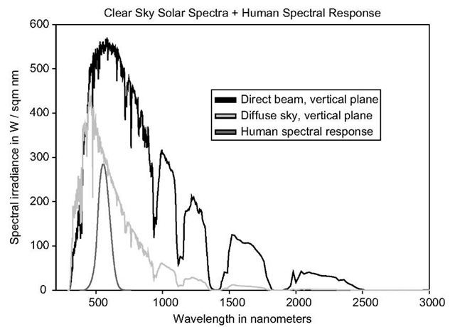
Spectra for direct beam and diffuse sky radiation on a vertical wall, with the sun 60° above the horizon on a clear day, are plotted in Fig. 1, along with a scaled plot of the human photopic visibility function. The sky is blue as a result of spectrally selective scattering of light from air molecules. This is seen in the shift of the diffuse sky spectrum in Fig. 1 toward shorter (bluer) wavelengths. Light through windows from blue sky alone does not appear strongly colored to the human observer. One reason is the adaptability of the human visual system. Another reason is the presence of a wide range of colors in sun and sky light, except for the case of sunlight at sunrise and sunset (which is reddish by virtue of the greater mass of intervening atmosphere, which removes some of the blue light in the spectrum). The solar spectrum under an overcast sky has a shape approximately the same as the sum of the direct and diffuse spectra, because scattering of light from water droplets in the atmosphere—the principal mechanism producing light from clouds and overcast skies—has weak spectral selectivity.
Electric lighting is approximately constant in output, in the absence of dimming systems. Daylight is changing constantly. The variability in sun and sky light is both a problem and a benefit in daylighting design. The benefit stems from the positive responses most people feel when experiencing the natural changes in daylight illumination in the absence of glare. The problem comes from the need to design the daylighting system to respond well to the changes. The design process begins with an understanding of the daylight availability for the building site, including the blocking effects of trees, buildings, and other nearby objects. Daylighting systems intended for an area experiencing predominantly overcast skies will be different from those designed for mostly clear-sky conditions. The National Renewable Energy Laboratory in Golden, Colorado in the United States and other national laboratories around the world, including weather bureaus and other such services, can be consulted for information about daylight availability for sites in their jurisdictions. In 1984 the Illuminating Engineering Society of North America published a guide to daylight availability.[2]
Glare
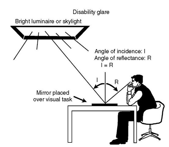
There are two kinds of glare, illustrated in Figs. 2 and 3. With disability glare, light reflecting from the surface of a visual task masks the contrast in that task and degrades the ability to see it. Examples include light reflected from a computer screen or television set and light reflected from a glossy magazine page. The reflected light reduces the contrast of the image. With a glossy magazine, for example, the reflected glare light can be as strong from the black ink as from the white paper, washing out the text and making it difficult or impossible to read.
Fig. 1 Direct and diffuse solar spectra on a vertical plane. The sky is clear, and the solar-altitude angle is 60°. Also shown is the photopic spectral luminous efficiency function, whose peak value is 1.0, scaled up for clarity.
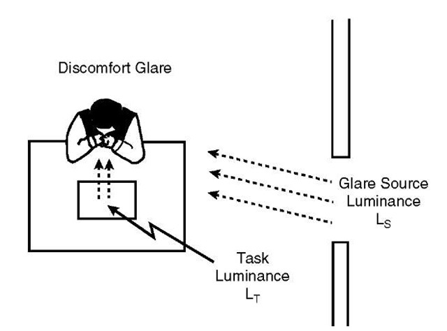
Discomfort glare usually results when light entering the eye from the side is much brighter than that coming from the visual task. This extra-bright light is mentally and physically confusing, and can result in visual fatigue, discomfort, and even headaches.
Buildings have several potential sources of glare. Beam sunlight entering the eye directly perhaps is the worst, due to its extreme brightness. Both specularly and diffusely reflected beam sunlight also can produce both kinds of glare. A bright window surrounded by dark walls and furnishings nearly always produces discomfort glare unless the light from the window normally does not enter the eyes, due to the orientation of the visual task. Bare electric lamps, either incandescent or fluorescent, can produce glare, as can poorly designed electric luminaires. A successful lighting design will reduce or minimize the system’s potential contribution to both kinds of glare, whether it be a daylighting or an electric lighting system.
Fig. 2 Disability glare is produced with a strong source of light that masks a visual task, usually by reflection, reducing its contrast and disabling the person’s ability to see that task well. Reorienting the task and the glare source often can ameliorate the problem, as can reducing the brightness of the source.
Fig. 3 Discomfort glare is produced by strong light from the side entering the eye without masking the target directly.
A variety of metrics have been devised in attempting to quantify visual comfort in the presence of discomfort-glare sources. Most incorporate terms for the angles of the brighter source from the direct line of sight into the eye.[3] A rule of thumb for reducing discomfort glare is to keep the brightest light source in the visual field from being stronger than a few times the general surround luminance.
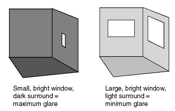
Fig. 4 illustrates two contrasting daylighting designs: one that promotes discomfort glare and one that ameliorates it. If the window in both cases looks out on the same uniform sky, it will have the same luminance in both cases. The larger window, therefore, will admit greater overall flux into the room. With moderately high room surface reflectances, this means that the room generally will be brighter and the room surface luminances will be closer to that of the window, producing less tendency toward glare. The same effect can be achieved by reducing the visible transmittance of the window while increasing the electric lighting in the room, reducing the contrast in room brightnesses, but this “solution” calls for more purchased energy.
A final caveat is offered regarding glare. One person’s “killer glare” is another person’s “sparkle.” People living in a region with persistent clouds and long, dark winters may have a much higher tolerance for direct beam admission than those living in a hot region with predominantly clear skies and high direct beam solar flux levels. It is important to use direct sunlight entry judiciously and with care to prevent the adverse impacts that can result. Some daylighting systems rely almost exclusively on direct beam sunlight, but these are designed to distribute the concentrated beams widely and diffusely, with minimal glare impact.
Fig. 4 Comparison of two daylighting designs. The one on the left has a relatively small window in a room with low surface reflectances, resulting in inadequate illumination, a gloomy appearance, and a propensity for discomfort glare. The one on the right, having larger window areas and higher surface reflectances, is brighter and less prone to glare.
DAYLIGHTING DESIGN
The goals of good daylighting include the provision of good-quantity and good-quality daytime interior illumination and view, coupled with high visual comfort for occupants. Happy people are productive people. It is necessary to prevent common problems such as unwanted glare and overheating from excessive direct beam illumination. In the process of providing good-quality illumination of adequate quantity, it is desirable to design the system so as to displace as much daytime electric lighting as possible, to minimize the energy costs of building operation.
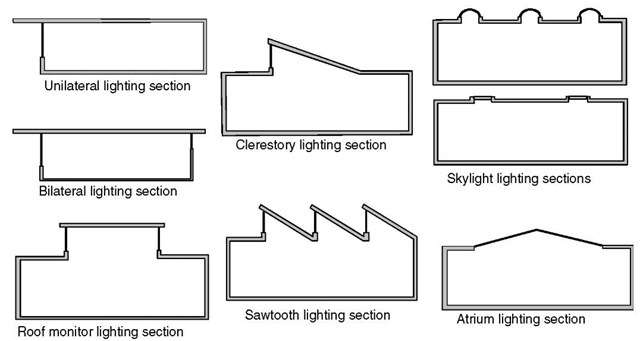
Some traditional means of admitting daylight into building spaces are drawn schematically in Fig. 5.
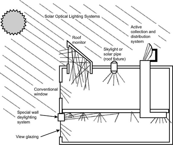
Additional approaches using light pipes and other beam-manipulation strategies can also be utilized. Several of these approaches are illustrated schematically in Fig. 6.
BUILDING OCCUPANCY
The most efficient buildings are unoccupied ones, with all the building’s energy services turned off. Consequently, the more a building is occupied and using energy, the greater are the opportunities for energy savings.
Daylighting design saves energy through averted electrical energy costs. If sufficient daylighting already is available in a building, however, additional daylighting could increase energy costs. On the other hand, health and comfort benefits often are sufficient to justify the introduction of some additional daylight if the extra energy costs are modest, limited by the use of high-performance windows.
If people are seldom in a building during the daylight hours, the need for illumination is minimal, and daylighting can’t save much energy. This typically is the case for most residences. Exceptions include residences occupied by retirees and others not working outside the home in the daylight hours, and those daytime-occupied homes suffering inadequate daylight-ing. In these cases, added daylighting makes good energy sense, and offers additional visual comfort and psychological benefits. For offices and other buildings fully occupied during daylight hours, daylight illumination often saves more building energy than any other single strategy, and the attendant increases in worker productivity add further to the benefits.
DAYLIGHTING SIMULATION AND MODELING
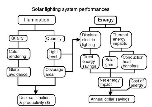
A flow chart showing the connections among various aspects of daylighting system energy and illumination performance is shown in Fig. 7.
Over the past two centuries, a variety of methodologies has been developed for predicting both the energy and the illumination performances of daylighting systems. With the advent of the fast personal computer, most of these methods have given way to sophisticated new computer tools for determining the performance of both electric and daylighting systems. The new tools include commercially available computer programs and public-domain software. A Web search on such terms as daylighting design software and architectural lighting design should provide links to many sites describing these computer programs.
Fig. 5 Section views of several ways daylight can be admitted into buildings.
Fig. 6 Illustration of the variety of ways daylight can be admitted into building spaces for controlled illumination of the interior.
Fig. 7 Connection pathways for the energy and illumination performance components of daylighting systems.
Another important tool is scale-model testing. Because illumination scales upward and downward well, small-scale models of buildings can be constructed of inexpensive materials. Light sensors can be placed inside these models to measure light levels when the models are placed in either simulated or natural daylight. Cameras also can be employed to image the light distributions inside the building’s daylit rooms, under varied sun and sky conditions, to assess performance visually.
CONCLUSION
Humans need connections with the outdoors. This need is built into our genetic makeup; it promotes health and a sense of well being, and makes us happier and more productive. Even photographs of nature on the wall have proved to be helpful.
According to Judith Heerwagen, principal of J.H. Heerwagen and Associates, and senior scientist at the Pacific Northwest National Laboratory in Seattle, in our evolutionary past, information about our environment had a pronounced influence on survival and health. Changes in daylight provided time cues and assessment of cloud formations for information about future weather conditions. These events influenced our ancestors’ daily decisions, such as where to sleep at night and where to look for food next week. Loss of illumination from and the view to the outdoors have been implicated in the poor recovery of patients in windowless intensive care units.
“Once you start thinking about it, [daylighting] design makes perfect sense,” Heerwagen has written. “We didn’t evolve in a sea of gray cubicles.”[4]
Daylighting offers a number of benefits to building owners and occupants. Cool, natural daylight has good color rendering; it is healthy and offers clear psychological benefits. Daylighting can displace electric lighting, saving energy and reducing air pollution, global warming, and our dependence on dwindling supplies of fossil-fuel energy.
Glossary
Brightness: Brightness is a subjective term with no universally acceptable quantitative definition. It refers to a perception of the strength of illumination received by the human eye. It may be used in general characterizations of the appearances of different sources and objects. Luminance approximately characterizes the strength of illumination emanating from an object or source, as perceived by the eye. Illuminance, Ev: The area density of luminous flux; the luminous flux per unit area at a specified point in a specified surface that is incident on, passing through, or emerging from that point in the surface (units: lm m_2 = lux). Irradiance, £e: The area density of radiant flux; the radiant flux per unit area at a specified point in a specified surface that is incident on, passing through, or emerging from that point in the surface (units: Wm~2). Luminance, Lv: The area and solid angle density of luminous flux; the luminous flux per unit projected area and per unit solid angle incident on, passing through, or emerging from a specified point in a specified surface, and in a specified direction in space (units: lm m_ 2 sr~1 = cd m _ 2). Luminous flux, v: The V( A )-weighted integral of the spectral flux 4>x over the visible spectrum (units: lumen or lm). Luminous intensity, /v: The solid angle density of luminous flux; the luminous flux per unit solid angle incident on, passing through, or emerging from a point in space and propagating in a specified direction (units: lm sr~1 = cd). Photopic spectral luminous efficiency function, V(A): The standardized relative spectral response of a human observer under photopic (cone vision) conditions over the wavelength range of visible radiation.
Radiance, Le: The area and solid angle density of radiant flux; the radiant flux per unit projected area and per unit solid angle incident on, passing through, or emerging from a specified point in a specified surface, and in a specified direction in space (units: W m~2 sr~*).
Radiant flux, e: The time rate of flow of radiant energy (units: watt).
Radiant intensity, /e: The solid angle density of radiant flux; the radiant flux per unit solid angle incident on, passing through, or emerging from a point in space and propagating in a specified direction (units: W sr_ *).
Radiation luminous efficacy, Kr: The ratio of luminous flux in lumens to radiant flux (total radiation) in watts in a beam of radiation (units: lumen/watt).
Spectral radiometric quantities: The spectral “concentration” of quantity Q, denoted Qx, is the derivative dQ/dX of the quantity with respect to wavelength A, where Q is any one of: radiant flux, irradiance, radiant intensity, or radiance (units: same as that of quantity Q per nm).
System luminous efficacy, Ks: The ratio of luminous flux in lumens delivered in a space to the electrical consumption of the lighting system delivering that flux (units: lumen/watt).
Visible transmittance, Tv or VT: The ratio of transmitted to incident illuminance on a glazing system; a unitless quantity.

