Abstract
Compressed-air energy storage (CAES) is currently being deployed as an alternative to lead-acid batteries for uninterruptible power supplies. These systems use compressed air supplied from either transport cylinders delivered by local gas services, or from stationary cylinders refilled from on-site compressors to drive a variety of economical expansion engine topologies. Several factors make these systems feasible for use in small-scale CAES systems for load leveling in conjunction with wind or solar energy generation while opportunities exist for improving cycle efficiency.
INTRODUCTION
Large-scale CAES has been successfully used as a means of peak shaving as an alternative to peaking gas turbines. Two such systems are the 290-MW unit in Huntorf, Germany[1] and the 110-MW unit in McIntosh, Alabama.1-2-1 These systems allow independent operation of the compression and expansion processes commonly found in conventional gas turbines. These systems have been called hybrid CAES; in that they continue to use fuel in the expansion process, the benefit being that the turbine need not produce power to drive the compressor when operating from the compressed air reserve. A disadvantage of these systems is that they require the use of fuel, which results in CO2 emissions, and the heat of compression is discarded thus compromising the cycle efficiency.
One solution to these issues is to use adiabatic compression and thermal energy storage (TES) in place of the combustion process associated with hybrid CAES. Systems employing adiabatic compression and energy storage were explored in the 1970s and have received renewed interest. One program titled Advanced Adiabatic Compressed Air Energy Storage (AA-CAES)[3] is underway in Europe, which is focused on zero-emission storage technology for centralized storage as well as modular products for distributed storage.
Several companies are now offering CAES systems in various configurations as environmentally friendly alternatives to the lead-acid batteries found in uninterruptible power supply (UPS) systems. Earlier this year, active power-introduced products for the UPS market based on its
Thermal and Compressed Air Storage (TACAS) technology.1-4-1 Several companies, including a major supplier of photovoltaic cells have expressed interest in the use of this technology for electricity storage generated by renewable sources. At this time, however, systems based on TACAS technology achieve cycle efficiencies between 10 and 15%, since it currently relies on oil-lubricated reciprocating compressors, which are nearly isothermal. This paper presents the current embodiment of the TACAS technology for UPS and discusses proposed enhancements to improve cycle efficiency for electricity storage.
THERMAL AND COMPRESSED AIR STORAGE FOR UPS
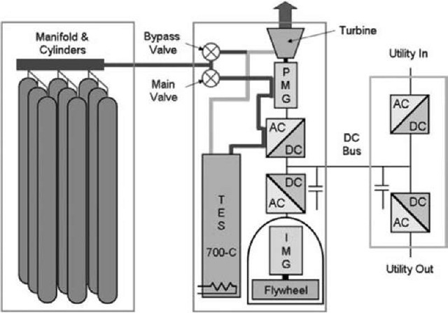
A CAES system with thermal energy supplied by the grid has been developed for UPS applications. The output of this system is 85 kW and is capable of delivering power for up to 15-min (21 kWh). A schematic of the system architecture is shown in Fig. 1.
The TACAS technology system uses high-pressure gas cylinders for air storage since volumetric energy density should be compatible with batteries for UPS applications and the use of caverns is impractical. The use of high temperature TES heated by the grid allows higher turbine inlet temperature than would, otherwise, be available from direct expansion of the air from cylinders.
The specific energy available from compressed air is a function of the turbine pressure ratio and inlet temperature. System sizing then becomes a tradeoff between the mass of gas stored in the cylinders and the mass of TES required to heat the gas being delivered to the turbine to achieve a desired inlet temperature. Cost optimization was performed to balance the size of the cylinder banks and TES as a function of the turbine pressure ratio, inlet temperature, and discharge temperature. The turbine pressure ratio was constrained by manufacturing capabilities and the discharge temperature was constrained to be suitable for discharge into an interior building space. Maximum storage pressure was constrained by the most economical cylinders and compressors as well as diminishing returns due to significant effects of gas compressibility effects (> 10%) above 310 bar [4500 psi].
Fig. 1 Thermal and compressed air storage (TACAS) technology for UPS.
Small-scale electric power and storage systems are generally more expensive to produce per kW and/or kWh output, so the optimization described above is essential. Furthermore, in order to meet system-cost targets, the simplest designs must be adopted.
EXPANSION TURBINE AND CONTROL
For small-scale systems, single-stage axial-flow impulse turbines offer an efficient and cost effective solution for high-pressure ratio expansion applications, particularly when direct-coupled to a high-speed permanent-magnet generator (PMG). A design speed of 70,000 rpm minimizes the PMG size helping to reduce the mass of expensive permanent magnet material and is a compromise between several machine design factors.
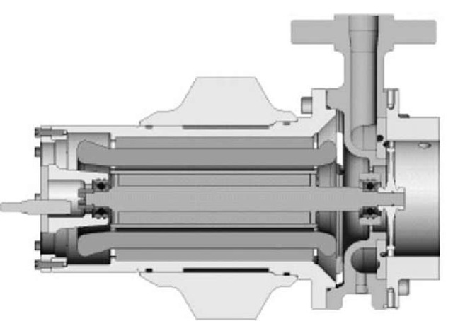
Fig. 2 100-kW single-stage axial-flow air turbine generator.
The system-optimized turbine shown in Fig. 2 operates at 385-psig and 230°C inlet temperature and delivers 100-kW shaft power at an efficiency of approximately 72% (small turbines typically have efficiencies between 70 and 80% whereas larger designs can approach 90%). Nearly the entire temperature drop occurs during expansion across the supersonic converging-diverging nozzles, so the temperature reaching the bladed disk approaches ambient. This allows the use of inexpensive rotor materials with integrally machined blades.
The single-stage turbine readily adapts to overhung-rotor architecture. The short overhang distance and short overall rotor length considerably simplify rotor-dynamic issues. In this particular configuration, rolling-element bearings with elastomer dampers are employed since the operational duty cycle for UPS is low. The design is easily configurable to foil-type gas bearings for higher duty service. Blade reaction is close to zero so axial bearing loads are very low and easily managed. Cooling of the bearing closest to the turbine inlet plenum is a challenge, but effective routing of air released from the control regulators helps to mitigate this. In fact, cooling of the turbine-PMG and its power converter is also provided by the process airflow.
Because the system is presently designed for UPS, transient response is of paramount importance. It takes about 1 s for the turbine-generator to reach full speed while carrying increasing load during the acceleration event. A small flywheel is used to “bridge” the gap between utility outage and full-load turbine output. This flywheel is configured with a bi-directional converter, which allows the flywheel to absorb step unloads and eliminates the need for unloading valves. During discharge, the flywheel also manages small power fluctuations so that turbine speed is held constant.
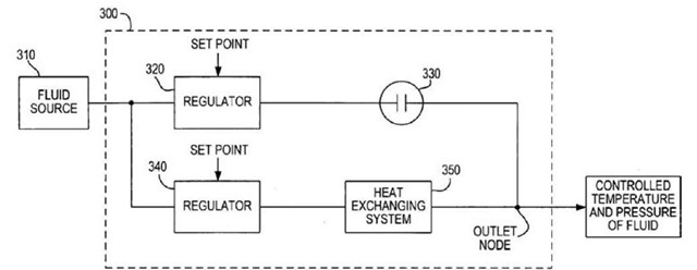
Simple turbines based on fixed nozzle geometry achieve power regulation through inlet pressure and temperature control. For this system, turbine inlet pressure and temperature are controlled by a pair of dome-loaded pressure regulators using a unique control scheme,[4'5] which routes air through or around the TES. Referring to Fig. 2, Main Regulator 340 controls airflow going to the Heat Exchanging System 350 (in this case, the TES). Bypass Regulator 320 controls airflow around the TES. Orifice 330 in the bypass path provides control stability. By combining flows through regulators 320 and 340 in varying proportions, constant fluid discharge temperature and pressure can be achieved throughout the sliding temperature range of the TES.
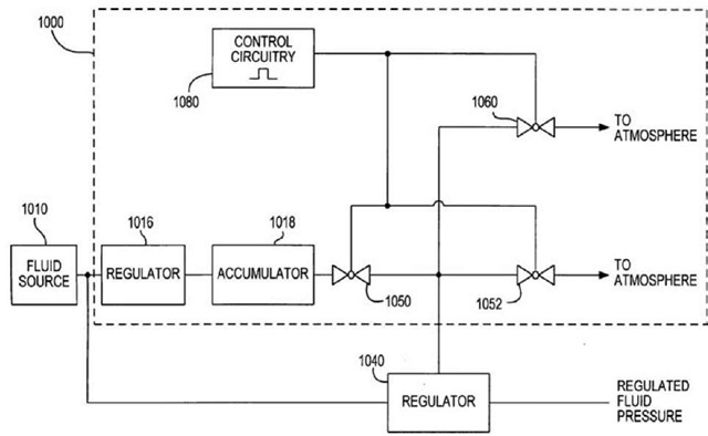
Regulators 320 and 340 identified in Fig. 3 are called dome-loaded regulators. This type of regulator is often employed when a high flow coefficient is needed. A dome-loaded regulator provides a discharge pressure equal to the pressure signal applied to the dome. Dome pressure control is provided by a combination of solenoid valves 1050 and 1052 in Fig. 3 that, respectively, either pressurizes the dome with air supplied by an upstream regulator and accumulator, or depressurizes the dome by venting the dome to atmosphere. Operation of these two valves is provided by a digital controller with feedback from downstream sensors. For reliable termination of dome pressure in emergency situations, a redundant NO solenoid valve 1060 is in line with an Emergency Power Off (EPO) circuit and is powered closed during normal operation. Faults such as sensed turbine over speed or manual EPO will de-power the valve and vent the dome causing the pressure regulator to close (Fig. 4).
THERMAL ENERGY STORAGE
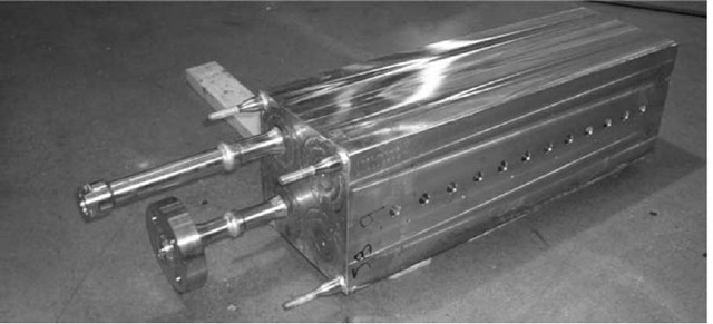
High-temperature thermal storage using 304 stainless steel provides extremely compact, robust, and low-risk TES when designed in accordance with American Society of Mechanical Engineers (ASME) rules. Although material cost is relatively expensive, manufacturing processes are simplified by integrating the thermal storage and pressure retention functions and an annular channel configuration[7] achieves very high heat transfer coefficients and heat extraction efficiencies (Fig. 5).
Advanced micro-porous insulation is used to prevent excess heat loss and provides a temperature gradient of over 600°C with approximately 25-mm thickness. Maximum operating temperature of 700°C is chosen based on life considerations for replaceable cartridge heating elements and creep considerations for the storage material based on estimated time at pressure and temperature. In the case of UPS, the expected cycling is low, but low-cycle fatigue due to dilatation stresses in the inlet piping when cold air from the regulators is introduced were investigated. These were found to be non-issues for UPS. For more extensive cycling that would be required for wind or solar storage, further investigation is needed. In addition, work is ongoing to identify more economical TES designs.
Fig. 3 Method of controlling constant turbine inlet temperature and pressure.
Fig. 4 Method of controlling constant fluid pressure.
Fig. 5 High energy thermal energy storage for UPS.
COMPRESSED AIR STORAGE IN VESSELS
Most large-scale CAES systems will probably continue to use underground caverns for pressurized air storage where available. However, for small-scale systems or where storage caverns are unavailable, small-storage vessels offer economies of scale due to mass production techniques employed. These cylinders are produced on automated process lines by backward extrusion of billet as opposed to larger vessels produced using seamless pipe with integrally forged heads. One manufacturer claims that the production rate for billet-formed cylinders is less than 30-s per cylinder.
In the United States, transport cylinders having Department of Transportation (DOT) exemption certification for 310-bar [4500-psi] service have been found most economical. Specific costs of less than $0.015 per bar-liter [$0.034 per psi-cu ft] can be obtained, whereas the cost of larger vessels has been found to be twice that or more. For the turbine inlet conditions being employed for UPS, this leads to energy cost for stored air of around $350/kWh. Energy storage costs for compressed air will decrease with increasing turbine inlet temperature. This must be balanced with the cost of the TES needed to achieve higher discharge temperatures.
In the United States, disagreement abounds on regulatory issues surrounding the on-site generation and storage of compressed air. Historically, stationary pressure vessels are designed to ASME standards, and installation and operation are regulated by the individual states. Transport vessels fall under the jurisdiction of the U.S. DOT and are exempted from state control. Many states allow the use of DOT vessels for stationary storage of air, but some do not and some have no regulations on pressure vessels. Attempts to qualify the most economical DOT designs through standard ASME channels have been fruitless since the two organizations’ design rules are not harmonized, even though the service seen by the cylinders is comparable. Furthermore, some jurisdictions assess permitting fees on a per vessel basis, whereas others will consider a bank of vessels as one installation and asses a flat fee. Therefore, some users in the United States must pay twice or more for air storage than others.
The regulatory picture for compressed air storage in vessels in Europe is much more favorable with the recent harmonization of the European Union and introduction of the Pressure Equipment Directive (PED). Through appropriate Notified body channels, it is a straightforward matter to re-qualify designs originally intended for one application into another application so long as the types of service are similar.
MODIFICATIONS TO TACAS TECHNOLOGY
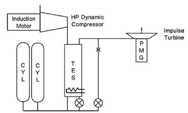
One of the most significant adaptations needed to improve TACAS technology for electricity storage is the development of a high-pressure adiabatic compressor and a slight modification to the system architecture to allow heat recovery. A schematic of the proposed architecture is shown in Fig. 6.
The exact form of the high-pressure compressor is under consideration. The high discharge temperatures imposed by adiabatic compression eliminates reciprocating compressors. Large-scale multi-stage centrifugal compressors with direct-drive induction motors have been used for high-pressure applications in the oil and gas industry. Scaling dynamic compressor designs for small-scale applications and adapting for high-discharge temperatures poses significant technical challenges, but will be crucial if high cycle efficiency is to be achieved.
Fig. 6 Schematic arrangement of modifications to thermal and compressed air storage technology architecture for improved cycle efficiency.
A further enhancement to the TACAS technology would allow higher turbine inlet temperatures since limitations on turbine-exhaust temperatures imposed by indoor discharge requirements of UPS could be relaxed. Increasing the discharge temperature reduces the TES discharge temperature range and so must be compensated by higher storage temperatures or additional TES mass for a given output. Further advances in TES material selection and design will be needed to achieve economic viability.
Finally, in applications for solar and wind energy storage, it may be possible to eliminate the bridging flywheel since the turbine has such rapid response. However, the excellent load regulation and speed control attributes of the flywheel in tandem with the turbine make this element of the architecture favorable if power quality enhancements are desired.
• Thermal energy storage cost reduction and or increase in allowable operating temperature.
Focus on these initiatives will allow consideration of TACAS technology for near-term electricity storage in conjunction with wind or solar power generating systems with lower upfront capital expenditure compared to large-scale systems.
SUMMARY
Compressed-air energy storage and TES system have been successfully integrated for UPS applications. Selected features of the TACAS technology are presented and enhancements for improving storage cycle efficiency are discussed. These enhancements include:
• Development of a small-scale high-pressure adiabatic compressor with high discharge temperature capability.
• Modification to thermal storage charge and discharge flow path.
• Turbine bearing upgrades for longer operational life.
• Turbine modifications for increased inlet and discharge temperatures.
