Abstract
This entry addresses the topic of building energy system simulation and touches on its importance, benefits, and relevance to the research, architecture, and engineering communities. The entry first gives an illustration of the different energy flow paths that occur in buildings and then describes the main features of the approaches that have evolved over the past four decades in an attempt to reach a solution to those energy flow paths. In addition, an overview of the simulation process in general terms is given, with certain simulation output parameters highlighted. The entry closes with real-life examples to give the reader a sense of some of the important applications of building energy system simulation programs.
INTRODUCTION
In the context of energy systems, the term building system simulation (BSS) refers to the application of computer programs designed specifically to simulate the energy systems that exist within buildings so that a realistic prediction of the thermal performance of a building can be achieved. The most common thermal performance parameters that are referred to by heating, ventilation, and air conditioning (HVAC) engineers are the peak cooling/heating load and energy consumption. The former can be used to determine the size of the HVAC system, whereas the latter can be used to determine the system’s energy efficiency. The main advantage of using BSS programs is that the thermal performance of the energy systems in a building can be determined and possibly optimized during the design stage.
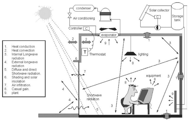
For any building, the main physical issues that need to be addressed by the BSS are shown in Fig. 1 in terms of energy flow paths, which can be summarized as follows:
• Surface convection represents the heat flow from an opaque surface to the adjacent air. This process occurs on both the internal and external surfaces of a building wall. The external convection process is influenced by the surface finish, wind speed, and direction, whereas the internal convection process is influenced by the forced air flow injected by the mechanical system serving the building zone and, in the absence of a mechanical system, is influenced by the buoyancy-driven natural convection.
• Inter-surface longwave radiation represents the amount of radiation, which is a function of surface temperatures, emitted from one surface to other visible surfaces, and is influenced by surface emissivity and geometry.
• The intensity of shortwave radiation on a surface is a function of time, surface geometry, and position of the sun relative to the geographical location of the building. The magnitude of shortwave radiation penetrating an opaque surface is influenced by the surface absorptivity and, in the case of transparent surfaces (i.e., glass), is influenced by surface absorptivity, transmissivity, and reflectivity.
• Shading caused by external obstructions to the sun-ray path affects the amount of solar radiation intensity on the external surface of an opaque element and the amount of shortwave radiation penetrating a transparent element, such as a window with overhang. In addition, the amount of solar radiation penetrating a transparent surface and the internal surfaces receiving this radiation are a function of the angle of incidence of the solar radiation and the geometry of the transparent surface, as well as the geometry of the internal surfaces.
• The process of air flow within buildings is affected by the building resistance to the unidirectional air leakage between outside to inside, by the amount of air being circulated among building zones, and also by air circulation within each zone. The amount of air leakage between the outside and the inside of the building is influenced by the external air boundary conditions (such as wind speed, pressure, and air temperature), and by the internal air temperature and pressure.
• There is also the process of casual heat gain from lighting fixtures, equipment, and people. This heat gain will constitute both radiative and convective components.
• The process of plant interaction with building zones affects their thermal comfort and can be caused by the action of a thermostat sensing and monitoring the zone’s air condition. The thermostat setting can be influenced by the building occupants or by the action of an automatic control mechanism.
• Control processes are caused by the response of a plant system to dynamically changing internal conditions. The plant response is influenced by the stream of signals constantly being fed back to the various controllers that actuate the appropriate control variable according to some control action.
• Moisture transfer processes are caused not only by internal generation processes and air migration from outside, but also by the condition of the air being injected into the zone by an air conditioning system.
• In buildings, it is also common to find movable features that can be used to control the effect of certain parameters on the indoor air, such as solar radiation and ambient air. Such features are influenced by social factors and by occupant comfort level.
HISTORICAL DEVELOPMENT
From the early 1960s until the late 1980s, many BSS programs have been developed to tackle the energy flow paths described earlier. These ranged from manual methods, in which the complexity of the real system is reduced to lessen the computational overhead and the input demands on the user, to highly sophisticated approaches in which mathematical models are constructed to represent the interactions observed in reality as closely as possible.
The evolution of design tools,[3] from the traditional to the present-day simulation approach, is summarized in Table 1. First-generation models focused on a simple “handbook” approach, which is piecemeal in that no coupling between the various discrete calculations was made. A steady-state U-value calculation may be conducted to evaluate envelope heat loss, for example; then a lookup table may be used to determine an allowance for zone solar gain; and finally, a degree-day relationship may be used to predict long-term energy requirements. In such calculations, many assumptions are encompassed to simplify their application. In addition, the calculations are based on steady-state, unidirectional wall heat flow, which rarely occurs in the real world.
Second-generation models took into account the temporal aspect of energy flow, especially in the case of elements with large time constants, such as in multilayered constructions. Analytical methods such as the response factor,[10] time, or frequency domain were applied based on the assumption that the building system is linear and possesses heat transfer properties that are time invariant. Modeling integrity remained low because of the decoupling and simplifying assumptions applied to the flow paths. Although the problem encountered with first-generation models related to quantifying transient heat conduction through multilayered constructions was overcome by second-generation models, a number of new problems emerged. These problems include the need for fast, powerful computers; an extensive input data set to define building geometry; and more appropriate user interfaces.
Fig. 1 Energy flow paths in buildings.
In recent years, numerical methods in third-generation models have played an increasingly important role in the analysis of heat transfer problems. Numerical methods can be used to solve complex, time-varying problems of high and low order. All fundamental properties are assumed to be time dependent, and coupling among the temporal processes is accounted for. The method allows for high-integrity modeling. Differential equation sets, representing the dynamic energy and mass balances within combined building and plant networks, are solved simultaneously and repeatedly at each (perhaps variable) time step as a simulation is conducted under the influence of control action. Modeling integrity has been increased so that the system is more representative of reality and is easy to use because of the improved graphical I/O (input/output) user interface. The highly transient nature and dynamic response of HVAC equipment are now fully taken into account.
TYPICAL APPLICATIONS
Building system simulation programs can be applied in many situations; they are used by researchers, engineers, and architects to solve real-life problems. In addition to the calculation of the peak cooling/heating loads and annual energy consumption, the following examples give a sense of other situations in which BSS can be a useful tool:
Table 1 Energy models evolution
• Predicting daylight levels within building spaces to minimize the energy consumed by artificial lighting and to improve visual comfort and productivity.
• Predicting the pattern of air distribution within spaces to optimize the air conditioning duct design.
• Predicting the effect of using innovative building envelope designs (such as vacuum-insulated wall panels and dual-skin facades) on the overall performance of buildings and on thermal comfort.
• Given a number of known energy conservation measures, BSS can be used to identify the most cost-effective option so that the capital investments are justified.
• For existing buildings, computer models can be developed and calibrated to determine the energy savings corresponding to alternative energy conservation measures or to alternative building and HVAC systems operational strategies.
• The impact of renewable technologies, such as solar collectors and photovoltaic, on energy consumption can be investigated.
• Application of passive heating/cooling concepts can be predicted easily by using simulation programs, and alterations to the building design can be made accordingly.
• The dynamic response of buildings when subjected to temporal boundary conditions can be investigated.
• Building system simulation are used extensively to develop codes and standards for energy conservation in different classes of buildings.
THE SIMULATION PROCESS
In any BSS program, the whole process can be represented by three main stages: model definition, simulation, and result analysis and interpretation, as indicated in Fig. 2. Depending on the level of detail, the building first has to be described in a manner that is acceptable to the program. The early versions of the DOE-2,[5] for example, required the use of a special description language to define the input parameters associated with the building under consideration. This required the user to learn the language in addition to learning the use of the simulation and output data analysis. To simplify the model definition process, graphical user interfaces (GUI) were later developed so that the errors at the input stage can be minimized. In any way, the input data describing the building and its systems then are fed to the solver (simulator) to perform the simulation according to a predefined schedule in which the simulation period and output parameters are specified. When the output is obtained from a simulation, it can be checked, and if necessary, the input stage may be repeated to rectify any errors made and to repeat the simulation. Even with the sophisticated GUIs available with many BSS programs, a verification procedure must be followed to ensure that the results of the simulation are reasonable and acceptable.
The most common input parameters required to simulate a building system are
• The weather data. Usually, this represents hourly data for many parameters, such as the dry bulb temperature; relative humidity; wind speed and direction; and diffuse, direct, and global solar radiation. A typical metrological year can be established to represent the weather pattern for a particular location, using at least 10 years’ worth of measured weather data.
• The building location. This can be established from the geographical location of the building site in terms of longitude and latitude.
• The building geometry. This is determined by defining each external surface’s geometry and orientation (walls and roofs).
• Building materials. The construction materials used in walls and roofs are defined in terms of layers, including the thermophysical properties such as the density, specific heat capacity, and thermal conductivity for each layer.
• Casual loads. Those are internal loads from lighting, appliances, and people, which are specified with a predefined schedule.
Fig. 2 The simulation process in terms of inputs and output.
• Shading devices. They could be used on an opaque surface (walls or roof) and transparent surfaces (windows and glass doors).
• Transparent surfaces. Their size, geometry, and optical properties (visible transmittance, solar transmittance, absorptance, and U-value) for both exterior and interior surfaces.
• Plant. This is the system used to maintain the internal environment of a building at a certain temperature and humidity, such as the HVAC system.
• Infiltration. This relates to the uncontrolled bidirectional flow between the inside of the building and the outside.
• Control. The control strategy adopted by the HVAC system can be defined by specifying the properties of the controller and the range of conditions to perform the control. In addition, lighting controls can be specified for situations in which daylight utilization may be required.
The input parameters mentioned above are adequate in most cases to perform the simulation. With some state-of-the-art BSS programs such as the ESP-r,[6] however, it is possible to define additional input data to allow addressing fairly complex issues if deemed necessary. It may be required, for example, to perform three-dimensional conduction analysis of a particular section within a building’s construction to estimate the impact of thermal bridging on the heat flow through the building’s envelope, which will require the definition of the domain in three-dimensional form.[2] In addition, a more accurate assessment of the infiltration levels and air movement between the building spaces may be necessary to arrive at a more realistic assessment of the thermal performance of the building, in which case an air flow network will need to be specified,[8] or if this was not adequate, a computational fluid dynamics calculation[12] can be incorporated to reach an even higher accuracy level. Furthermore, the effect of environmental systems dynamics can be investigated in detail using BSS programs such as EnergyPlus,[4] ESP-r, HVACSIM + ,[9] and TRNSYS.[13] Such BSS programs were designed to study the transient effect of both the HVAC systems and the building, and with some programs, it is even possible to use smaller simulation time steps for the HVAC simulation because the HVAC systems exhibit time constants that are much smaller than the building structure.
When the input parameters are defined, the simulator performs the calculations, based on the adopted mathematical approach, to generate the output required by the user. It is possible to perform the analysis at the whole-system level (i.e., the building and plant systems) or at the system level (the building or plant), or down to the component level (i.e., a cooling coil, a fan, a window, a wall, etc.). Some of the outputs that can be obtained are shown in Fig. 2. These outputs include:
• Thermal comfort. This is at the whole-system level and is a very important parameter for many buildings. The simulation output can indicate whether the space in question has an acceptable thermal comfort condition for the occupants.
• Annual energy requirements. This is also at the whole-system level, which gives an indication of the total electrical energy consumed by the HVAC system (another source of energy, such as gas or oil, can also be included) and by the lighting and equipment or appliances used in the building.
• Detailed energy balance of building components. This is at the component level, for which the output data can be studied to investigate the thermal performance of individual building components such as walls, roof, and windows.
• Peak load requirements. This information is important because it is used to size the HVAC systems for a building. It is common to perform the calculation on the building system first to determine the peak cooling/ heating load required and then to utilize the output to perform a whole-plant and building analysis to determine the peak electrical demand for the whole plant and building system.
• Breakdown of load contributors. This information is useful to identify the major load users so that countermeasures of more significant impact on energy use may be introduced.
To realize the benefits of BSS programs in real-life situations, two examples are discussed in the following sections. The examples focus mainly on how the problem was addressed and also on how to utilize the simulation output so that the set objectives can be achieved. The detailed input data fed to the BSS program to conduct the simulations in the examples were not addressed, because the data are fairly detailed and will not serve the purpose.
EXAMPLE 1
The dayroom area of a hospital in Scotland suffers from high temperature during summer. The dayroom area is joined to the dining-room area and consists of windows with large glazing area. The occupants of the dayroom are elderly patients, who are not always capable of judging thermal stress and so would be unlikely to leave the dayroom when overheating occurs or to take corrective action by, for example, opening a window. The objective of this study was to advise on possible modifications to the hospital ward to better control its radiation and temperature environment.[7]
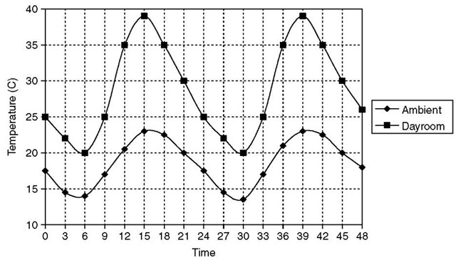
A base case test was conducted for a typical Glasgow summer weather pattern for the period of Wednesday, July 7 to Thursday, July 8. In this test, it was assumed that all the blinds were open in the dayroom and that a fixed infiltration rate of one air change per hour prevailed. Shading analysis was performed to take into account any obstructions and overhangs. The resulting temperatures are shown in Fig. 3. As indicated, the thermal stresses in the dayroom are significant. In reality, it is unlikely that fixed infiltration will occur, because this will depend on many factors, such as the magnitude of open windows, cracks, vents, and so on, as well as changes in pressures and temperatures across the building envelope. For this reason, an air flow network was set up in which the dayroom was represented by nodes on two vertical levels to account for temperature stratification; other air nodes were added to represent wind-induced pressures on the various facades. Then the air flow network nodes were connected by flow components to represent cracks, windows, and doors.
Fig. 3 Base case with no blinds and one air change per hour.
Initially, it was assumed that windows in the dayroom would remain open at all times. The effect of opening and closing of windows in the dining room, however, was considered subsequently by the addition of components to represent flow control. The control action taken was to open a window when the adjacent indoor air node temperature exceeded 20°C. This action was applied to the dining room. An extract fan component was also defined and was set to be thermostatically controlled so that air was extracted from the dayroom’s upper point (hottest level) if the upper-level temperature exceeded 25°C, and the hot air was exhausted through the west wall.
A plant was also set up to represent the heating system, which is expected to be operating when room temperatures are below the desired heating set point temperature of 21°C. The drop in temperature below the heating set point occurs because it was assumed that dayroom windows are open all the time and, thus, ambient air free cooling takes place. The plant consisted of oil-filled electric radiators located at the appropriate zones. Each zone has a radiator with a heating capacity sufficient to bring the zone temperature to the heating set point. The dayroom was fitted with a 3000 W electric radiator, whereas the dining room was fitted with a 5000 W unit. Note that these values were arrived at by conducting an initial simulation without the plant. The heating output was split into 40% convective and 60% radiative.
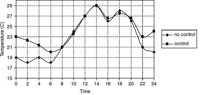
It should be noted that the building, plant, and fluid flow arrangement was arrived at after a number of runs using different control schemes. The results for the predicted room temperature are shown in Fig. 4.
Fig. 4 Predicted dayroom temperature with plant and mass flow network with and without control on dayroom windows.
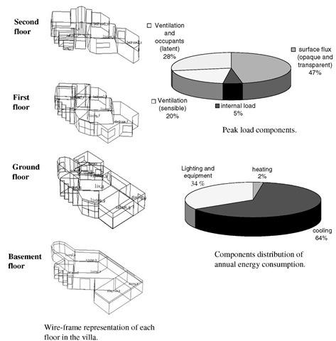
Shading analysis for the assembled villa.
Fig. 5 The different stages required, with detailed building energy analysis programs.
Fig. 4 shows that for the case with no control, the dayroom temperature is lower than the dining-room temperature when there is no solar radiation. The dayroom temperature increases during the day to a level slightly higher than the dining-room temperature. Heating takes place when the dayroom and dining-room temperatures fall below 21°C. A drop in the dayroom’s upper-level temperature occurs in midmorning because that is when the extraction fan is activated by the thermostatic controller. With this building, plant, and flows arrangement, it was possible to decrease the dayroom temperature with respect to the base case. It also was possible to reduce the amount of heating required by the heating system if control also was imposed on the dayroom windows so that they remain closed if the dayroom temperature fell below a certain level. To achieve this, an additional flow component was considered in the simulation to represent flow control so that the window is closed if the dayroom temperature falls below 20°C. The predicted temperatures are also shown in Fig. 4 by the curve with control. The total heating required during the simulation period and in the case where the dayroom windows were left open was 102.2 kWhrs, compared with 39.5 kWhrs for the window-control case.
EXAMPLE 2
A private residential villa located in Kuwait City consists of large glazed areas and complex shading structures. For such villas, solar insulation is a concern because the weather in Kuwait City is typically hot, with a long summer extending over seven months when air conditioning is required. The number of cloudy days during the summer is almost negligible. Therefore, the electricity provider requested the investigation of the thermal performance of the villa when subjected to a number of energy conservation measures.[1] The plot has an area of 800 m2, with the villa’s constructional floor area being 1127 m2, and is characterized by a sunspace. The external glazing area is 250 m2 with a glazing to total external wall area ratio of 22%.
Fig. 5 shows that the villa has a complex geometrical shape with a complex shading structure. For this reason, a detailed shading analysis was carried out to account for the effect of the shading structures on solar insolation. In addition, annual simulations were conducted for the cases considered, which include:
Base case: Use double tinted glass and no insulation on columns and beams.
Case 1: Add thermal insulation to exposed floors.
Case 2: Reduce window area by 20%.
Case 3: Use double reflective glass.
Case 4: Reduce air change by 50%.
Case 5: Columns and beams fully insulated.
Case 6: Use more energy efficient lighting.
Case 7: Combine case-1, case-3 and case-5.
Case 8: Combine case-4, and case-7.
Case 9: Combine case-2, and case-8.
Case 10: Combine case-2, and case-7.
For each case, the peak cooling demand and annual energy consumption were predicted by the BSS program. The peak cooling load was normalized over the living floor area so that it could be considered in updating the existing limit stipulated in the Kuwaiti code of practice for energy conservation in buildings.[11] It was possible from the simulation results to determine which conservation measure(s) to consider and what alterations were required so that the villa’s thermal performance could be improved significantly over the base case design.
In addition, by including the cost factor, a cost/benefit analysis was performed, using the actual cost of implementing the energy conservation measure and using the simulation output to reflect the savings in terms of the initial cost of the air conditioning equipment and the cost of energy over the life cycle of the building. This gave a clear picture of the options that could be considered based on certain criteria (energy, cost, or both). A similar analysis was conducted on a number of other private villas, and the results of the normalized peak cooling load were used to update the limits for such buildings in the code of practice for energy conservation. This limit is of paramount importance because it is referred to by HVAC engineers to determine the maximum capacity of the air conditioning system; the limit can also be verified by the concerned authority for compliance with the code.
CONCLUSION
Building system simulation programs have evolved into more sophisticated tools over the past few decades. The developments made focused not only on the user interface level, but also on the mathematical approach adopted, leading to more accurate and realistic predictions of the thermal response of buildings. Building system simulation have wide applications for engineers, architects, and researchers. They are valuable tools that can be used to investigate the impact of numerous energy measures on the overall performance of buildings. State-of-the-art BSS tools allow for integrated building design, which consequently leads to designs that are optimized for thermal and visual comfort and for energy efficiency.
