Median Filtering on the TI C6416 DSK
Two median filtering C64x programs can be found on the CD in the Chap4\median_filter directory. Both use the infrastructure developed in the previous topic, where DMA is used to page blocks of image data into internal RAM, those scan-lines are filtered, and then the processed pixels are paged out to external RAM, again via DMA. These programs share two common files, the median_filter.cmd linker command file (the contents of which are identical to the C64x DSK linear filtering programs of 4.4) and image . h, which initializes the in_img buffer with a noisy "Barbara" image (corrupted with 15% shot noise).
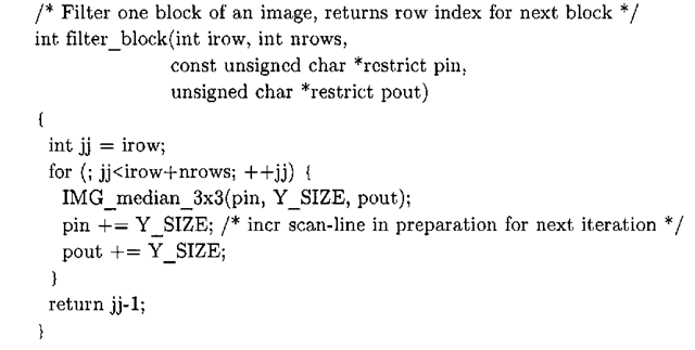
The first program, located in the MedianFilterCCS_3x3 subdirectory, uses the IMGLIB function IMG_median_3x3 to implement a 3×3 median filter. Apart from removing a few C pre-processor macros and definitions that are no longer needed, median_f ilter_3x3. c is very similar to blur3x3_imglib_paging_dma. c (see Listing 4-7). The only function that changes in any significant fashion is filter_block. This function, shown in Listing 4-13, calls IMG_median_3x3 to pass nrows number of image rows (starting at pin), through a 3×3 median filter.
Listing 4-13: filter block function in median filter3x3.c.
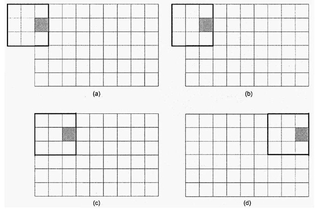
IMG_median_3x3 works in a row-major fashion6’11. This is best illustrated by example, as shown in Figure 4-22. For the first two iterations, default data is used for computation of the median, until the filter slides over enough such that it completely fits over a portion of the image data (iteration 2). As a result, in contrast to the earlier filtering programs where the first and last columns of the output image are ignored, in this implementation the first two columns of the processed image are meaningless and should be ignored.
Figure 4-22. IMG_median_3x3 across a single row (shaded box denotes output pixel), (a) Iteration 0, where the 1st two columns of the median neighborhood are filled with default values, (b) Iteration 1, where the 1st column of the neighborhood consists of default values, (c) By iteration 2, the mask has slid over enough such that the entire neighborhood consists of pixels from the input image. This is the first valid output pixel in this row. (d) Final iteration for the current row. With the next iteration, the entire mask slides down a single row and then proceeds to march across the subsequent row.
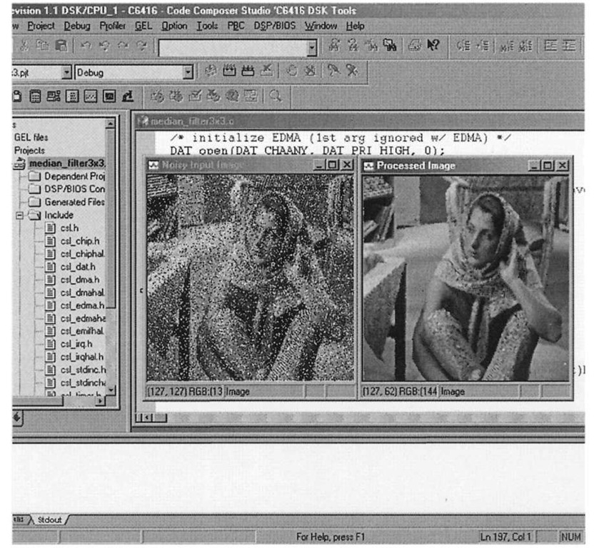
IMG_median_3x3 is not as general as the IPP function used in the preceding section, and there are times when a median filter larger than 3×3 is desired. Figure 4-22 shows the result of processing the noisy "Barbara" image using IMG_median_3x3 (the image displays are created using the procedure described in 4.3.1). There remain a few speckles in the processed image, due to the filter size being too small to handle the noise density of the input image. Passing this same image through a 5×5 median filter will further attenuate the effects of the shot noise, albeit at greater cost to the overall "sharpness" of the output.
A C64x program that uses the minimum exchange network for a 5×5 median filter can be found in the directory Chap4\median_filter \MedianFilterCCS_5x5. The overall structure of the source code for this program is very similar to that of the 3×3 case, with the major difference being the inclusion of the partial sorting C code for a 25-element list within filter_block, which is more or less taken verbatim from the implementation of MedianFilter: : process Image5x5.
Figure 4-23. Using IMG_median_3x3 to process clean up an image with 15% shot noise.
It should be mentioned that compiling median_filter_5x5.c with release configuration optimizations enabled on a 2 GHz Pentium 4 workstation takes approximately 15 minutes. As discussed in 2.1.1, the TI C6x line of DSPs are based on a VLIW architecture. VLIW differs from traditional CISC and in some respects RISC architectures in that it places the burden on the software (compiler) more so than the hardware to provide optimal performance. With VLIW architectures, it is up to the compiler to schedule instructions so that complete fetch packets are generated. This means that there are no NOP instructions within the VLIW instruction and in this way the DSP’s functional units are fully utilized. The loop kernel in filter block for the 5×5 median filter has a large number of comparisons – the compiler has to perform substantial dependency analysis in order to generate instruction packets that make use of the DSP’s functional units to the fullest extent.


