Introduction
The most apparent properties of metals, their luster and their color, have been known to mankind since metals were known. Because of these properties, metals were already used in ancient times for mirrors and jewelry. The color was utilized 4000 years ago by the ancient Chinese as a guide to determine the composition of the melt of copper alloys: the hue of a preliminary cast indicated whether the melt, from which bells or mirrors were to be made, already had the right tin content.
The German poet Goethe was probably the first one who explicitly spelled out 200 years ago in his Treatise on Color that color is not an absolute property of matter (such as the resistivity), but requires a living being for its perception and description. Applying Goethe’s findings, it was possible to explain qualitatively the color of, say, gold in simple terms. Goethe wrote: "If the color blue is removed from the spectrum, then blue, violet, and green are missing and red and yellow remain." Thin gold films are bluish-green when viewed in transmission. These colors are missing in reflection. Consequently, gold appears reddish-yellow.
This topic treats the optical properties from a completely different point of view. Measurable quantities such as the index of refraction or the reflectivity and their spectral variations are used to characterize materials. In doing so, the term "color" will almost completely disappear from our vocabulary. Instead, it will be postulated that the interactions of light with the valence electrons of a material are responsible for the optical properties. As in previous topics, where an understanding of the electrical properties was attempted, an atomistic model and later a quantum mechanical treatment will be employed. Thus, the electron theory of metals, as introduced in the first six topics, will serve as a foundation.
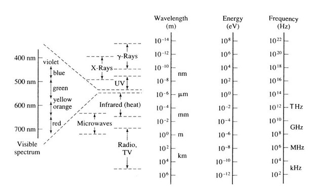
Light comprises only an extremely small segment of the entire electromagnetic spectrum, which ranges from radio waves, via microwaves, infrared, visible, ultraviolet, and X-rays, to g rays, as depicted in Fig. 10.1. Many of the considerations that will be advanced in this topic are therefore also valid for other wavelength ranges, e.g., for radio waves or X-rays.
At the beginning of this century the study of the interactions of light with matter (black body radiation, etc.) laid the foundations for quantum theory. Today, optical methods are among the most important tools for elucidating the electron structure of matter. Most recently, a number of optical devices, such as lasers, photodetectors, waveguides, light-emitting diodes, flat-panel displays, etc., have gained considerable technological importance. They are used in communication, fiber optics, medical diagnostics, night viewing, solar applications, optical computing, or for other optoelectronic purposes. Traditional utilizations of optical materials for windows, antireflection coatings, lenses, mirrors, etc., should be likewise mentioned. All taken, it is well justified to spend a major part of this topic on the optical properties of materials.
Before we start our discourse, we need to define the optical constants. We make use of some elements of physics.
Figure 10.1. The spectrum of electromagnetic radiation. Note the small segment of this spectrum that is visible to human eyes.
Index of Refraction, n
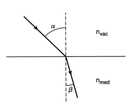
When light passes from an optically "thin" into an optically dense medium, one observes that in the dense medium, the angle of refraction, b, (i.e., the angle between the refracted light beam and a line perpendicular to the surface) is generally smaller than the angle of incidence, a see Fig. 10.2. This well-known phenomenon is used for the definition of the refractive power of a material and is called Snell’s law,
Commonly, the index of refraction for vacuum, nvac, is arbitrarily set to be unity. The refraction is caused by the different velocities, c, of the light in the two media,
Thus, if light passes from vacuum into a medium, we find
The magnitude of the refractive index depends on the wavelength of the incident light. This property is called dispersion. In metals, the index of refraction varies, in addition, with the angle of incidence. This is particularly true when n is small.
As can be seen in Table 10.1, the index of refraction is not always larger than 1 as for example, for metals. Likewise, for X-rays, n can be smaller than 1.
In summary, when light passes from vacuum into a medium, its velocity as well as its wavelength, l, generally decrease in order to keep the frequency, and thus, the energy, constant.
Figure 10.2. Refraction of a light beam when traversing the boundary from an optically thin medium into an optically denser medium.
Table 10.1. Optical Constants for Some Materials (1 = 600 nm).
|
n |
k |
W (nm) |
R%b |
|
|
Metals |
|
|
|
|
|
Copper |
0.14 |
3.35 |
14.2 |
95.6 |
|
Silver |
0.05 |
4.09 |
11.7 |
98.9 |
|
Gold |
0.21 |
3.24 |
14.7 |
92.9 |
|
Aluminum |
0.97 |
6.0 |
7.9 |
90.3 |
|
Ceramics |
||||
|
Silica glass (Vycor) |
1.46 |
a |
3.50 |
|
|
Soda-lime glass |
1.51 |
a |
4.13 |
|
|
Dense flint glass |
1.75 |
a |
7.44 |
|
|
Quartz |
1.55 |
a |
3 x 10⁸ |
4.65 |
|
Al2O3 |
1.76 |
a |
7.58 |
|
|
Polymers |
||||
|
Polyethylene |
1.51 |
a |
4.13 |
|
|
Polystyrene |
1.60 |
a |
5.32 |
|
|
Polytetrafluoroethylene |
1.35 |
a |
2.22 |
|
|
Semiconductors |
||||
|
Silicon |
3.94 |
0.025 |
1,910 |
35.42 |
|
GaAs |
3.91 |
0.228 |
209 |
35.26 |
aThe damping constant for dielectrics is about 10 7.
bThe reflection is considered to have occurred on one reflecting surface only.
Damping Constant, k
Metals damp the intensity of light in a relatively short distance. Thus, to characterize the optical properties of metals, an additional materials constant is needed.
We make use of the electromagnetic wave equation, which mathematically describes the propagation of light in a medium. The derivation of this wave equation from the well-known Maxwell equations does not further our understanding of the optical properties. (The interested reader can find the derivation in specialized texts.1)
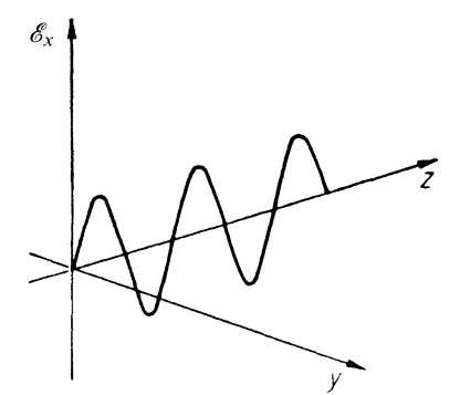
For simplification, we consider a plane-polarized wave that propagates along the positive z-axis and which vibrates in the x-direction (Fig. 10.3). We neglect possible magnetic effects. For this special case, the electromagnetic wave equation reads2
where Ex is the x-component of the electric field strength,3 e is the dielectric constant,4 s is the (a.c.) conductivity and e0 is a constant, called the permittivity of empty space (see topic 4).
Figure 10.3. Plane-polarized wave which propagates in the positive z-direction and vibrates in the x-direction.
The solution to (10.4) is commonly achieved by using the following trial solution:
where E0 is the maximal value of the electric field strength and o = 2pn is the angular frequency. Differentiating (10.5) once with respect to time, and twice with respect to time and z, and inserting these values into (10.4) yields
Equation (10.6) leads to an important result: The index of refraction is generally a complex number, as inspection of the right-hand side of (10.6) indicates. We denote for clarity the complex index of refraction by n. As is true for all complex quantities, the complex index of refraction consists of a real and an imaginary part,
In the literature, the imaginary part of the index of refraction, n2, is often denoted by "k" and (10.7) is then written as
We will call n2 or k the damping constant. (In some topics n2 or k is named the absorption constant. We will not follow this practice because the latter term is extremely misleading. Other authors call k the attenuation index or the extinction coefficient, which we will not use either in this context.) Values for k for some materials are given in Table 10.1.
Squaring (10.8) yields, together with (10.6),
Equating individually the real and imaginary parts of (10.9) yields two important relations between electrical and optical constants,
Let us return to (10.9). The right-hand side is the difference between two dielectric constants (a real one and an imaginary one). Thus, the left side must be a dielectric constant too, and (10.9) may be rewritten as
Equating individually the real and imaginary parts in (10.12) yields
and (with (10.11))
Similarly as above, e1 and e2 are called the real and the imaginary parts of the complex dielectric constant, e, respectively. (e1 in (10.13) is identical to e in (10.10).) e2 is often called the absorption product or, briefly, the absorption.
We consider a special case: For insulators (s « 0) it follows from (10.11) that k « 0 (see also Table 10.1). Then (10.10) reduces to e = n2 (Maxwell relation).
From (10.10), (10.11), (10.13), and (10.14) one obtains
It should be emphasized that (10.10)-(10.16) are only valid if e, s, n, and k are measured at the same wavelength, because these "constants" are wavelength dependent. For small frequencies, however, the d.c. values for e and s can be used with good approximation, as will be shown later. Finally, it should be noted that the above equations are only valid for optically isotropic media; otherwise e becomes a tensor.
We return now to (10.5) in which we replace the index of refraction by the complex index of refraction (10.8). This yields
which may be rewritten to read
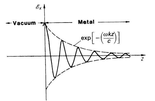
Equation (10.18) is now the complete solution of the wave equation (10.4). It represents a damped wave and expresses that in matter the amplitude decreases exponentially with increasing z (Fig. 10.4). The constant k determines how much the amplitude decreases, i.e., k expresses the degree of damping of the light wave. We understand now why k is termed the damping constant.
The result which we just obtained is well known to electrical engineers. They observe that at high frequencies the electromagnetic waves are conducted only on the outer surface of a wire. They call this phenomenon the (normal) skin effect.
Figure 10.4. Modulated light wave. The amplitude decreases exponentially in an optically dense material. The decrease is particularly strong in metals, but less intense in dielectric materials, such as glass.


