Experimental Results and Their Interpretation
Pure Metals
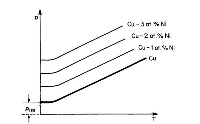
The resistivity of a metal, such as copper, decreases linearly with decreasing temperature until it reaches a finite value (Fig. 7.7) according to the empirical equation
where a is the linear temperature coefficient of resistivity. We postulate that thermal energy causes lattice atoms to oscillate about their equilibrium positions, thus increasing the incoherent scattering of the electron waves (or equivalently, increasing the number of electron-atom collisions). The residual resistivity, pres, is interpreted to be due to imperfections in the crystal, such as impurities, vacancies, grain boundaries, or dislocations. The residual resistivity is essentially not temperature-dependent. According to Matthiessen’s rule the resistivity arises from independent scattering processes which are additive, i.e.,
Figure 7.7. Schematic representation of the temperature dependence of the resistivity of copper and various copper-nickel alloys. pres is the residual resistivity.
The thermally induced part of the resistivity, pth, is called the ideal resistivity, whereas the resistivity that has its origin in impurities (pimp) and defects (pdef) is summed up in the residual resistivity. The number of impurity atoms is generally constant in a given metal or alloy. The number of vacancies or grain boundaries, however, can be changed by various heat treatments. For example, if a metal is annealed at temperatures close to its melting point and then rapidly quenched into water at room temperature, its room-temperature resistivity increases noticeably due to quenched-in vacancies. Frequently, this resistance increase diminishes during room-temperature aging or annealing at slightly elevated temperatures due to the annihilation of some vacancies. Likewise, recrystallization, grain growth, and many other metallurgical processes change the resistivity of metals. As a consequence of this, and due to its simple measurement, the resistivity is one of the most widely studied properties in materials research.
It is interesting to compare the thermally induced change in conductivity in light of the quantum mechanical and classical models. The number of free electrons, Nf, essentially does not change with temperature. Likewise, N(E) changes very little with T. However, the mean free path, and thus the relaxation time, decreases with increasing temperature (due to a large rate of collisions between the drifting electrons and the vibrating lattice atoms). This, in turn, decreases s according to (7.15) and (7.26), in agreement with the observations in Fig. 7.7. Thus, both models accurately describe the temperature dependence of the resistivity.
Alloys
The resistivity of alloys increases with increasing amount of solute content (Fig. 7.7). The slopes of the individual p versus T lines remain, however, essentially constant. Small additions of solute cause a linear shift of the p versus T curves to higher resistivity values in accordance with Matthiessen’s rule. This resistivity increase has its origin in several mechanisms. First, atoms of different size cause a variation in the lattice parameter and, thus, in electron scattering. Second, atoms having different valences introduce a local charge difference that also increases the scattering probability. Third, solutes which have a different electron concentration compared to the host element alter the position of the Fermi energy. This, in turn, changes the population density N(E) according to (6.8) and thus the conductivity, see (7.26).
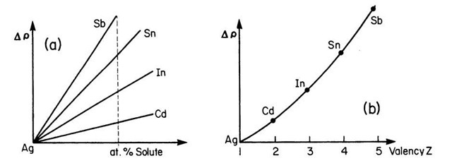
Various solute elements might alter the resistivity of the host material to different degrees. This is demonstrated in Fig. 7.8. Experiments have shown that the resistivity of dilute single-phase alloys increases with the square of the valence difference between solute and solvent constituents (Linde’s rule, Fig. 7.8(b)).
Figure 7.8. Resistivity change of various dilute silver alloys (schematic). Solvent and solute are all from the fifth period. (a) Resistivity change versus atomic % solute and (b) resistivity change due to 1 atomic % of solute.
Thus, the electron concentration of the solute element, i.e., the number of additional electrons the solute contributes, clearly plays a vital role in the resistance increase, as already mentioned above.
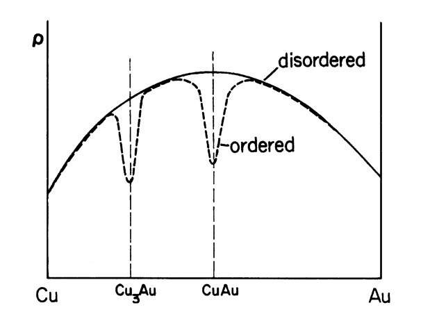
The isothermal resistivity of concentrated single-phase alloys often has a maximum near 50% solute content, as shown in Fig. 7.9 (solid line). Specifically, the residual resistivity of these alloys depends, according to Nordheim’s rule, on the fractional atomic compositions (XA and XB) of the constituents
where C is a materials constant. Nordheim’s rule holds strictly only for a few selected binary systems, because it does not take into consideration the changes in the density of states with composition.
Figure 7.9. Schematic representation of the resistivity of ordered and disordered copper-gold alloys.
This is particularly true for alloys containing a transition metal.
The resistivity of two-phase alloys is, in many instances, the sum of the resistivities of each of the components, taking the volume fractions of each phase into consideration. However, additional factors, such as the crystal structure and the kind of distribution of the phases in each other, must also be considered. The concentration dependence of the resistivity of two-phase alloys does not exhibit a maximum, as in Fig. 7.9, but resembles instead a linear interpolation between the resistivities of the individual phases.
Some alloys (copper with small amounts of iron, for example) show a minimum in the resistivity at low temperatures. This anomaly is due to additional scattering of electrons by the magnetic moments of the solutes and is a deviation from the Matthiessen rule (Kondo effect).
The property of certain materials to conduct electricity, albeit with some resistance, is utilized for resistors in electrical circuits (to limit the current flow), or for generating heat (strip heaters, portable radiators, furnaces, etc.). The "Joule heating", or power, P, thus produced is proportional to the resistance of the wire and the square of the current:
One common type of resistor is made from carbon-composites. Others are wire-wound, for example, around a ceramic body. They employ alloys of high resistivity (about 10~4 O cm), such as nichrome (nickel-chromium), and need to withstand corrosion and be suitable for high temperatures. Other resistors may consist of metal films on glass or ceramic substrates. Integrated circuits use silicon technology for the same purpose. Resistors having a fixed value are color-coded to indicate their nominal resistance, the tolerance of this value, and the rated wattage (see table in topic 4). Variable resistors, having a sliding contact, are either wire-wound or of the carbon-composite type.
Ordering
Solute atoms are generally randomly distributed in the solvent. Thus, the number of centers where incoherent scattering occurs increases proportionally with the number of substitutional atoms. If, however, the solute atoms are periodically arranged in the matrix, i.e., if, for example, in a 50/50 alloy the A and B atoms alternately occupy successive lattice sites, then the electron waves are coherently scattered. This causes a decrease in resistivity (and an increase in the mean free path) (Fig. 7.9). Only selected alloys, such as Cu3Au, CuAu, Au3Mn, etc., show a tendency towards long-range ordering.
The ordered state can be achieved by annealing an alloy of appropriate composition slightly below the order-disorder transition temperature (about 395°C in Cu3Au) followed by a moderate cooling rate, or by slowly cooling from above the transition temperature. Long-range ordering causes super-lattice lines in X-ray patterns.
The disordered state can be obtained at room temperature by quenching the alloy rapidly in ice brine from slightly above the transition temperature. Annealing above this transition temperature destroys the ordering effect. In some alloys, however, such as in CuAu, the tendency towards ordering is so strong that even near the melting point some ordering remains.
Some alloys, such as a-copper-aluminum, exhibit a much smaller resistance decrease by annealing below a certain ordering temperature. This effect is called short-range ordering and has been found to be due to small domains in which the atoms are arranged in an ordered fashion. In the short-range ordered state the A-B interactions are slightly stronger than the A-A or B-B interactions. (Short-range ordering can be identified by using small-angle X-ray scattering. It causes small and broad intensity increases between the regular diffraction lines.4)
Superconductivity
Superconductors are materials whose resistivities become immeasurably small or actually become zero below a critical temperature, Tc. The most sensitive measurements have shown that the resistance of these materials in the superconducting state is at least 1016 times smaller than their room temperature values. (See, in this context, Fig. 7.1.) So far, 27 elements, numerous alloys, ceramic materials (containing copper oxide), and organic compounds (based, e.g., on selenium or sulfur) have been discovered to possess super-conductivity (see Table 7.1). Their Tc values range between 0.01 K and 134 K. Some metals such as cesium become superconducting only if a large pressure is applied to them. The superconducting transition is reversible. The superconducting state has to be considered as a separate state, distinct from the liquid, solid, or gaseous states. It has a higher degree of order—the entropy is zero.
Seventy-five years after the first discovery of superconductivity in mercury (H.K. Onnes, Leiden/Holland, 1911) a new class of superconductors was found by Bednorz and Muller (Zurich/Switzerland, 1986) which involved copper oxide-based ceramics. These materials displayed a transition temperature almost twice that of what has been known so far. This observation triggered an immense research effort virtually everywhere in the world involving billions of dollars in research money and thousands of scientists who competed for finding the most advantageous superconducting compound.
Table 7.1. Critical Temperatures of Some Superconducting Materials.
aThe designation "1-2-3 compound" refers to the molar ratios of rare earth to alkaline earth to copper. (See chemical formula.)
As a result of this endeavor, within a few years, new copper oxide-based compounds were found that were named 1-2-3 superconductors because of the characteristic molar ratios between rare earth to alkaline earth to copper (see Table 7.1). Eventually, ceramic materials having critical temperatures above 77 K were synthesized, which were euphorically called "high-Tc superconductors." Superconductors having a Tc above 77 K (boiling point of liquid nitrogen) are technologically interesting because they do not require liquid helium (boiling point 4 K) or liquid hydrogen (boiling point 20 K) for cooling.
Recently, a new class of superconductors, which is based on layers of iron and arsenic (among others) has been discovered. Examples are parent compounds consisting of LaOFeAs, BaFe2As2, FeSe, and iron phosphide. In many respects, these so called pnictides (i.e. compounds of the nitrogen group), also called iron-based superconductors or ferropnictides have some properties similar to the cuprates (compounds based on copper anions). LaOFeAs is not superconducting, but becomes superconducting when some of the oxygen is replaced by up to 11% fluorine (Tc = 26 K). Replacing the lanthanum with cerium, samarium, neodymium and/or praseodymium leads to a Tc of about 52 K. Doped FeSe has a Tc of 8 K at normal pressure and a Tc of 27 K under high pressure. Moreover, the parent compound is antiferromagnetic. This property is destroyed by increased doping, leading to superconductivity. But there also exist differences among the cuprates. The mechanisms still need to be sorted out.
A zero resistance combined with high current densities makes superconductors useful for strong electromagnets, as needed, e.g., in magnetic resonance imaging devices (used in medicine), high-energy particle accelerators, or electric power storage devices. (The latter can be appreciated by knowing that once an electrical current has been induced in a loop consisting of a superconducting wire, it continues to flow without significant decay for several weeks.) Further potential applications are lossless power transmission lines, high-speed levitated trains, more compact and faster computers, or switching devices called cryotrons. (The latter device is based on the destruction of the superconducting state in a strong magnetic field, see below).
Despite the above-mentioned discoveries and achievements, superconducting electromagnets for high magnetic fields are, as of this writing, still manufactured from "old-fashioned" Nb-Ti or Nb3Sn alloys (and not from ceramic superconductors) for reasons which will be discussed in the next section. The wires for the electromagnets are composed of fine filaments of a Nb-Ti alloy, each of which is only micrometers in diameter. They are imbedded in a matrix of nearly pure copper (for flexibility). We shall cover the basic concepts for these applications in the following sections.
Experimental Results
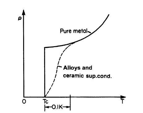
When the temperature of a superconducting material is lowered, the transition into the superconducting state is generally quite sharp for pure and structurally perfect elements (Fig. 7.10). A temperature range of less than 10-5 K has been observed in pure gallium. In alloys, however, the transition may be spread over a range of about 0.1 K. Ceramic superconductors generally display an even wider spread in transition temperatures.
The transition temperature, Tc, often varies with the atomic mass, ma, according to
where a is a materials constant (Isotope effect).
Figure 7.10. Schematic representation of the resistivity of pure and impure superconducting elements. Tc is the transition or critical temperature.
As an example, Tc for mercury varies from 4.185 K to 4.146 K when ma changes from 199.5 to 203.4 atomic mass units.
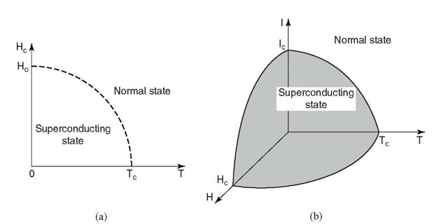
Elimination of the superconducting state does not only occur by raising the temperature, but also by subjecting the material to a strong magnetic field. The critical magnetic field strength, Hc, above which superconductivity is destroyed, depends upon the temperature at which the material is held. In general, the lower the sample temperature, the higher the critical field Hc (Fig. 7.11(a)). One finds
where H0 is the critical magnetic field strength at 0 K. Ceramic superconductors usually have a smaller Hc than metallic superconductors, i.e., they are more vulnerable to lose superconductivity by a moderate magnetic field.
As already mentioned above, one of the main applications of superconductors is in wires for the windings of high-strength electromagnets. We will learn in topic 14 that considerable currents are needed for these large field strengths. Now, conventional wires, when passed by large currents, generate substantial amounts of resistive heating, see (7.30), which needs to be removed somehow, for example, by water cooling. On the other hand, superconducting wires that have a zero resistance below Tc are free of the resistive power loss. In this case, however, a cooling below Tc is still needed. In practice, it is a weighting between acquisition price and operation cost which commands the decision whether a superconducting or a normal electromagnet is used.
Figure 7.11. (a) Dependence of critical field strength, Hc, at which superconductivity is destroyed, in relation to the temperature of the specimen. (b) The limits of superconductivity are defined in a critical T-H-I-diagram.
One limiting factor for ultrahigh field strengths is that the magnetic field thus produced can reach Hc, so that the superconducting state is eventually destroyed by its own magnetic field. Moreover, another limiting parameter exists, namely, the critical current, Ic, above which superconductivity disappears. All taken, an interrelationship between temperature, current, and magnetic field strength is observed: an increase in one of these parameters decreases the critical value of the remaining two. In other words, superconductivity is only present when temperature, magnetic field strength, and current remain within a "critical space" in a T-H-I-diagram, as depicted in Fig. 7.11(b).
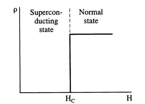
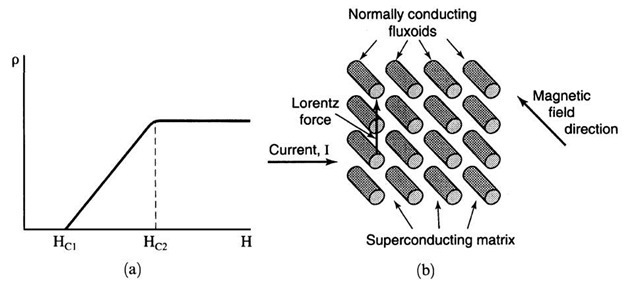
Two classes of superconducting materials are distinguished. In type I superconductors the destruction of the superconducting state by a magnetic field, i.e., the transition between the superconducting and normal state, occurs sharply (Fig. 7.12). The critical field strength Hc is relatively low. Thus, type I superconductors are generally not used for coils for superconducting magnets. In type II superconductors the elimination of the superconducting state by a magnetic field is gradual. The superconducting properties are extended to a field Hc2, which might be 100 times higher than Hcl (Fig. 7.13(a)). Because of this stronger resistance against the magnetically induced destruction of the superconducting state, type II superconductors are mainly utilized for superconducting solenoids. Magnetic fields of several tens of tesla (hundreds of kilogauss) have been achieved with these materials. Among the type II superconductors are transition metals and alloys consisting of niobium, aluminum, silicon, vanadium, lead, tin, titanium, and, in particular, Nb3Sn or Nb-Ti. Ceramic superconductors also belong to this group. (The terms "type I or type II superconductors" are often used likewise when the abrupt or gradual transition with respect to temperature is described, see Fig. 7.10).
Figure 7.12. Schematic representation of the resistivity of a type I (or soft) superconductor when a magnetic field of field strength H is applied. These solids behave like normal conductors above Hc.
Figure 7.13. (a) Schematic representation of the resistivity of a type II (or hard) superconductor. The region between Hc1 and Hc2 is called the vortex state. Above Hc2, the solid behaves like a normal conductor. (b) Schematic representation of fluxoids in a superconducting matrix.
The interval between Hc1 and Hc2 represents a state in which superconducting and normal conducting areas are mixed in the solid. Specifically, one observes small circular regions, called vortices or fluxoids, which are in the normal state and which carry the smallest possible unit of a magnetic flux, called a flux quantum,
The vortices are surrounded by large, superconducting regions.
The fluxoids are parallel to the magnetic field lines and are regularly arranged in space, thus forming essentially a two-dimensional superlattice (Fig. 7.13(b)). (The regular arrangement of the fluxoids stems mainly from the fact that they repel each other.) One would therefore expect that a current which flows perpendicular to these fluxoids (as is the case for electromagnets) would always find an unobstructed path through the superconducting matrix and thus would exhibit unlimited superconductivity. However, since the current in an electromagnet flows at a right angle to the magnetic field, a so-called Lorentz force is created, which pushes the fluxoids perpendicular to the current and the magnetic field directions see Fig. 8.11. Thus, the moving fluxoids may become obstacles for the drifting electrons. As a result, the current is reduced, or equivalently, the electrical resistance is increased. The obstruction does not occur, however, when the fluxoids are pinned to their positions, for example, by microstructural inhomogeneities in the matrix, such as grain boundaries, dislocations, or fine particles of the alloying components. This fluxoid pinning has been achieved by heat treatment and by plastic deformation, for example, by wire drawing. It is the basis for the presently used Nb3Sn superconducting magnets.
Fluxoid pinning and resultant large critical currents have not yet been achieved in ceramic superconductors. The reason for this lies in the fact that thermally induced lattice vibrations make fluxoid pinning at higher temperatures (100 K) considerably more difficult than at much lower temperatures.
It is noted in passing that superconducting materials have exceptional magnetic properties. For example, a permanent magnet levitates in mid-air above a piece of a superconducting material that is cooled below Tc. We shall return to the magnetic properties of superconductors in Section 15.1.1.
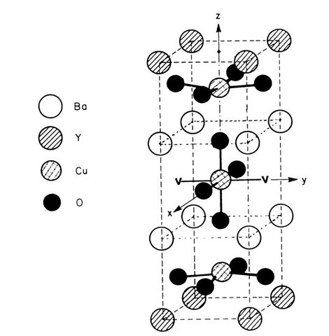
Ceramic superconductors seem to be characterized by two-dimensional sheets of atoms, a Cu-O nonstoichiometry (i.e., a limited amount of an oxygen deficiency, see Fig. 7.14), a reduced lattice parameter between the copper atoms, and a tetragonal (high temperature) to orthorhombic (below room temperature) transition. Only the orthorhombic modification is superconducting. Further, ceramic superconductors appear to be antiferromagnetic (see Section 15.1.4). Thus, the superconductivity is most likely connected to the entire lattice structure.
Figure 7.14. Room-temperature unit cell of YBa2Cu3O7_x. The structure is an orthorhombic layered perovskite (BaTiO3) containing periodic oxygen vacancies. Two examples for oxygen vacancies are indicated by a "V."
Despite their considerably higher transition temperatures, ceramic superconductors have not yet revolutionized new technologies, mainly because of their inherent brittleness, their incapability of carrying high current densities, and their environmental instability. These obstacles may be overcome eventually, e.g., by using bismuth-based materials that are capable of carrying high currents when cooled to about 20 K or by utilizing composite materials, i.e., by inserting the ingredient oxide powders into silver tubes and sintering them after plastic deformation (e.g., wire pulling). Other techniques employ depositions of ceramic superconducting films on ductile substrates. Additions of silver into some ceramic superconductors improve their environmental stability (by reducing the porosity of the material) without lowering Tc. In any event, the further development of superconducting materials should be followed with great anticipation.


![tmp6C335_thumb[2] tmp6C335_thumb[2]](http://what-when-how.com/wp-content/uploads/2011/07/tmp6C335_thumb2_thumb.jpg)
![tmp6C339_thumb[2] tmp6C339_thumb[2]](http://what-when-how.com/wp-content/uploads/2011/07/tmp6C339_thumb2_thumb.jpg)
