Introduction
The problem of guided wave propagation in a wave guide with imperfectly reflecting boundaries arises in several applications, such as propagation in mine tunnels and in screened surface wave guides. In recent years, many studies have been carried out on the propagation characteristic of radio waves in tunnels in UHF band [1-2]. From the theoretical point of view, tunnels can be regarded as hollow waveguides surrounded by a lossy dielectric medium, such as concrete, ground, and so on. The problem of radio communication in tunnels has found solutions using leaky transmission lines as supports for propagation of transverse electromagnetic modes [3-4]. These modes are characterized by the fact that there is no cutoff frequency, and by an attenuation which increases with increasing frequency. However, when the frequency is high enough, natural propagation modes, which are transverse electric or transverse magnetic, can appear and interfere with the transmission line supported transverse electromagnetic modes [5].
Natural propagation can be helpful to solve some specific problems, such as radio communications in mines with rooms and pillars which cannot be solved easily with the help of transmission lines. Natural propagation modes are also useful for short range communications, for example, in some road tunnels. For distances shorter than 200m, these modes can be more suitable the transmission line supported modes [6].
In order to maximize the performance attainable feeding in the interior of tunnels with antenna systems, it is important to estimate the value and the attenuation of the electromagnetic strength inside the tunnel. Investigations concerning radiowave propagation in railways tunnels have been performed [7] and the results confirm the existence of a waveguide effect strongly related to the antenna positions. Recently, Abo-Seida et al. [8] and Abo-Seida [9] studied the electromagnetic field due to vertical magnetic dipole buried in stratified media. Also, Abo-Seida [10] computed the attenuation below and above the cutoff frequency in a rectangular tunnel.
It might be thought that waveguides with circular cross sections would be preferred to guides with rectangular cross sections, just as circular pipes are commonly used for carrying water and fluids in preference to rectangular pipes. However, circular waveguides have the disadvantage that there is only a very narrow range between the cutoff wavelength of the dominant mode and the cutoff wavelength of the next higher mode. As with rectangular guides, the modes may be classified as transverse electric ( TE ) or transverse magnetic ( TM ), according to whether it is the electric or magnetic lines of force that lie in planes perpendicular to the axis of the guide. The different modes are designated by a double subscript system analogous to that for rectangular guides.
Geometrical structure and basic equations
The concrete tunnel is practically of finite thickness. At low frequencies, below cutoff frequencies, the skin depth may exceed this thickness and thus the field penetrates to the outside. However, our aim is to check the possibilities of radio communication in tunnels and to replace the tunnel by a circular waveguide. It is possible to make this replacement in practical problems involving conducting walls.
A uniform waveguide of circular cross section is most conveniently described by polar coordinate system (r , ^, z ), and divide the possible solutions for circular guides into transverse magnetic and transverse electric waves. For the TM waves Hz is identically zero and the wave equation for Ez is used. Also, TE waves Ez is identically zero and Hz is used. The modes are further labeled by a two-dimensional order number ( m, n ). For a circular waveguide with a radius r the critical frequencies are given by
where m > 0 , Ymn and Ymn are the nth zero of Bessel function Jm and of its derivative, respectively, and C = 3 x 10⁸ ms_1 is the speed of light.
The cutoff wavelengths are given for a circular waveguide by [11]
where m,n are equal to 1,2,3,…….. for the TMmn modes, and equal to 0,1,2,3,…….. for the TEmn modes.
Below the lowest cutoff frequency, propagation is not possible. The attenuation a is independent of the electrical properties of the wall and have the form equation
where Xc is the longest cutoff wavelength of the waveguide and the value 8.69 is the decibels of attenuation per unit length.
Above its cutoff frequency, the attenuation a for the TMmn modes is given by [11]
and for the TEmn modes, this attenuation a is given by
where 1 £ is the intrinsic impedance of the propagation medium and equal to
is the conductivity of the guide walls in mho/m, | is the permeability of the propagation medium in henry/m, e is the permittivity of the propagation medium in farad/m.
Determination of the attenuation constant
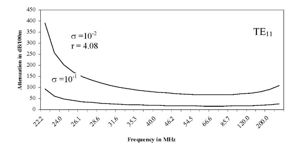
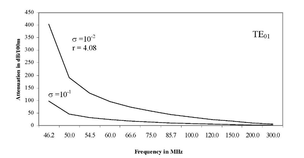
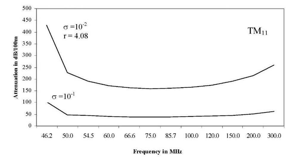
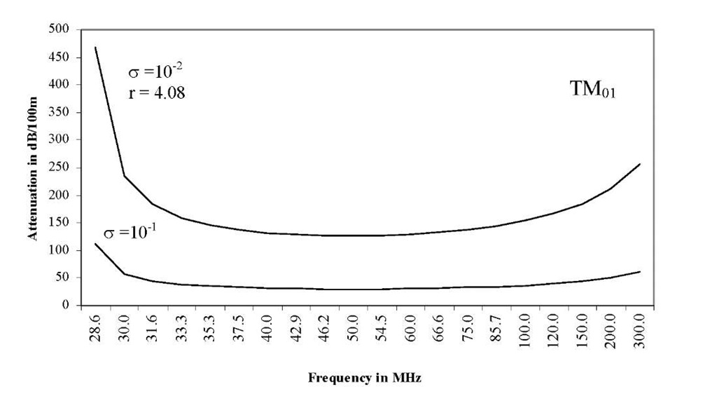
We consider the circular -waveguide model of the tunnel. In practice, the concrete tunnel wall is of finite thickness. This tunnel is considered to have a radius r = 4.08 m. Its conductivity is taken as 10_1 and10~2 mho/m as in [10].
The cutoff frequency is 20 MHz corresponding to approximately a tunnel shaped as a circular cylinder, inside it a wave is propagating in the TE11 mode. Taking account of the conductivity of the walls, the attenuation constants of the TE11 and TE01 modes have been determined and the results plotted in Figs (1) and (2), respectively, for both values of g and for frequencies in the range 20-300 MHz. As in the case of TEmn modes, the attenuation of the electromagnetic waves is calculated for both the TM11 and TM01 modes. The obtained results are plotted in Figs (3) and (4), respectively, as a function of the frequency.
Fig. 2. Frequency and attenuation in a circular tunnel
Fig. 4. Frequency and attenuation in a circular tunnel
Conclusion
The propagation of electromagnetic waves in a circular tunnel have been performed and the results confirm the existence of a waveguide effect strongly related to the antenna positions. The cutoff frequency was calculated and three different types of frequency ranges were characterized. The numerical results presented here indicate that the different values of m and n modes.
This work enable us to distinguish three different ranges of frequency, characterized by three different propagation mechanisms.


