10.8.2
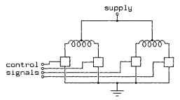
Typical controllers for unipolar stepping motors are variations on the outline shown in Fig. 10.39.As in Fig. 10.37, boxes are used to represent switches; a control unit, not
shown, is responsible for providing the control signals to open and close the switches at the appropriate times in order to spin the motors. The control unit is commonly a computer or programmable interface controller, with software directly generating the outputs needed to control the switches.

FIGURE 10.39 Typical controller for unipolar stepping motors.

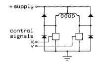
FIGURE 10.40 Hybrid drive with diode shunt suppression.

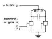
FIGURE 10.41 Hybrid drive with capacitive suppression.
As with drive circuitry for variable-reluctance motors, we must deal with the inductive kick produced when each of these switches is turned off. Again, we may shunt the inductive kick using diodes, but now four diodes are required, as shown in Fig. 10.40.
The extra diodes are required because the motor winding is not two independent inductors; it is a single center-tapped inductor with the center tap at a fixed voltage. This acts as an autotransformer. When one end of the motor winding is pulled down, the other end will fly up, and vice versa. When a switch opens, the inductive kickback will drive that end of the motor winding to the positive supply, where it is clamped by the diode. The opposite end will fly downward, and if it was not floating at the supply voltage at the time, it will fall below ground, reversing the voltage across the switch at that end. Some switches are immune to such reversals, but others can be seriously damaged.
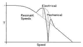
A capacitor may also be used to limit the kickback voltage, as shown in Fig. 10.41. The rules for sizing this capacitor are the same as the rules for sizing the capacitor shown in Fig. 10.38, but the effect of resonance is quite different. With a PM motor, if the capacitor is driven at or near the resonant frequency, the torque will increase to as much as twice the low-speed torque. The resulting torque-speed curve may be quite complex, as illustrated in Fig. 10.42.

FIGURE 10.42 Effect of resonance on motor performance.
Figure 10.42 shows a peak in the available torque at the electrical resonant frequency and a valley at the mechanical resonant frequency. If the electrical resonant frequency is placed appropriately above what would have been the cutoff speed for the motor using a diode-based driver, the effect can be a considerable increase in the effective cutoff speed.
The mechanical resonant frequency depends on the torque, so if the mechanical resonant frequency is anywhere near the electrical resonance, it will be shifted by the electrical resonance. Furthermore, the width of the mechanical resonance depends on the local slope of the torque-speed curve. If the torque drops with speed, the mechanical resonance will be sharper, while if the torque climbs with speed, the mechanical resonance will be broader or even split into multiple resonant frequencies.
