10.11.1
Previously, torque and back-emf expressions are developed considering just one motor phase. When there is more than one phase, each individual phase acts independently to produce torque. Consider the two-phase motor illustrated in Fig. 10.71. Power dissipated in the phase resistances produces heat; the phase inductances store energy but dissipate no power; and power absorbed by the back-emf sources EA and EB is converted to mechanical power Tm. (Think about it: where else could it go?) Writing this last relationship mathematically gives
![]()

Thus, the mutual torque produced is a function of the back-emf waveforms and the applied currents. Most important, Eq. (10.2) applies instantaneously. Any instantaneous variation in the back-emf waveforms, or the phase currents will produce an instantaneous torque variation.
Equation (10.2) provides all the information necessary to design drive schemes for the two-phase motor. Since the back-emf waveforms are a function of position,it
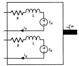
FIGURE 10.71 Two-phase motor schematic.
is convenient to consider Eq. (10.2) graphically. Making the simplifying assumption that the emf is an ideal square wave, Fig. 10.72 shows the back-emf waveforms, with
![]()
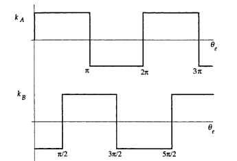
FIGURE 10.72 Square-wave back-emf waveforms for a two-phase motor.
One-Phase-On Operation. Given the waveforms shown in Fig. 10.72,several drive schemes become apparent. The first, shown in Fig. 10.73, is one-phase-on operation where only one phase is conducting current at any one time. In this figure, the phase currents are superimposed over the back-emf waveforms and Eq. (10.2) is applied instantaneously to show the resulting motor torque on the lower axes. The overbars are used to signify current flowing in the reverse direction. Some important aspects of this drive scheme include the following:
• Ideally, constant ripple-free torque is produced.
• The shape of the back-emf of the phase not conducting at any given time (e.g., phase A over 3n/4 <6< 5n/4) has no influence on the torque production since the associated current is zero. The back-emf need only be flat when the current is applied.The smoothing of the transitions in the back-emf that exist in a real motor do not add torque ripple.
• Neither phase is required to produce torque in regions where its associated back-emf is changing sign.
• Each phase contributes an equal amount to the total torque produced. Thus each phase experiences equal losses and the drive electronics are identical for each phase.
• Copper utilization is said to be 50 percent, since at any time only half of the windings are being used to produce torque; the other half have no current flowing in them.
• The amount of torque produced can be varied by changing the amplitude of the current flowing in them.

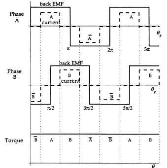
FIGURE 10.73 One-phase-on torque production.
Two-Phase-On Operation. Following the same procedure used to construct Figs. 10.73 and 10.74 shows two-phase-on operation, where both phases are conducting at all times. Important aspects of this drive scheme include the following:
• Ideally, constant ripple-free torque is produced.
• The shape of the back-emf is critical at all times, since torque is produced in each phase at all times.
• If either current does not change sign at exactly the same point that the emf does, negative phase torque is produced, which leads to torque ripple.
• Both phases are required to produce torque in regions where their associated back-emf is changing sign.
• Each phase contributes an equal amount to the total torque produced. Thus, each phase experiences equal losses, and the drive electronics are identical for each phase.
• Copper utilization is 100 percent.
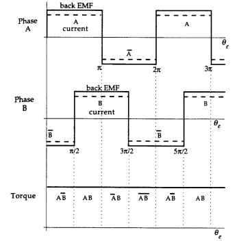
FIGURE 10.74 Two-phase-on torque production.
• The amount of torque produced can be varied by changing the amplitude of the square-wave currents.
^ Impossible-to-produce square-wave currents are required.
• For a constant torque output, the peak phase current is reduced by half compared with the one-phase-on scheme.
The Sine-Wave Motor. A square-wave back-emf motor driven by square current pulses in either one- or two-phase-on operation as previously described represents what is usually called a brushless dc (BLDC) motor. On the other hand, if the back-emf is sinusoidal, the motor is commonly called a synchronous motor. Operation of this motor follows Eq. (10.2) also. However, in this case it is easier to illustrate torque production analytically. The key to understanding the two-phase syn-

Thus, once again the torque produced is constant and ripple-free. In addition, the currents are continuous, and only finite di/dQ is required to produce them. Just as in the square-wave case considered earlier, the currents must be synchronized with the motor back-emf. To summarize, important aspects of this driven scheme include the following:
• Ideally, constant ripple-free torque is produced.
• The shape of the back-emf and drive currents must be sinusoidal.
• If both phase currents are out of phase an equal amount with their respective back-emf the torque will have a reduced amplitude but will remain ripple-free.
• Each phase contributes an equal amount to the total torque produced. Thus, each phase experiences equal losses, and the drive electronics are identical for each phase.
• Copper utilization is 100 percent.
• The amount of torque produced can be varied by changing the amplitude of the sinusoidal currents.
• The phase currents have finite di/dQ.
Based on the three examples just considered, it is clear that there are an infinite number of ways to produce constant ripple-free torque. All that is required is that the left-hand side of Eq. (10.2) instantaneously sum to a constant. The trouble with the square-wave back-emf schemes is that infinite di/dQ is required. The torque ripple that results from not being able to generate the required square pulses is called commutation torque ripple. The trouble with the sinusoidal emf case is that pure sinusoidal currents must be generated. In all cases, the back-emf and currents must be very precise whenever the current is nonzero; any deviation from ideal produces torque ripple. For the square-wave back-emf schemes, position information is required only at the commutation points (i.e., 4 points per electrical period). On the other hand, for the sinusoidal back-emf case, much higher resolution is required if the phase currents are to closely follow the back-emf waveforms. Thus, simple and inexpensive Hall-effect sensors are sufficient for the brushless dc motor, whereas an absolute position sensor (e.g., an absolute encoder or resolver) is required in the sinusoidal current drive case.
Despite the fact that the square-wave back-emf schemes inevitably produce torque ripple, they are commonly implemented because they are simple and inexpensive. In many applications, the cost of higher performance cannot be justified.
H-Bridge Circuitry. Based on Figs. 10.73 and 10.74, it is necessary to spend positive and negative current pulses through each motor winding. The most common circuit topology used to accomplish this is the full-bridge or H-bridge circuit, as shown in Fig. 10.75. In the figure, Vcc is a dc supply, switches S1 through S4 are commonly implemented with MOSFETs or IGBTs (though some still use bipolar transistors
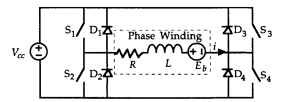
FIGURE 10.75 H-bridge circuit.
because they are cheap), diodes D1 through D4, called freewheeling diodes, protect the switches by providing a reverse current path for the inductive phase current, and R, L, and Eb represent one motor phase winding.
Basic operation of the H bridge is fairly straightforward. As shown in Fig. 10.76a, if switches S1 and S4 are closed, current flows in the positive direction through the phase winding. On the other hand, when switches S2 and S3 are closed, current flows in the negative direction through the phase winding, as shown in Fig. 10.76b. In either case, the current climbs exponentially according to the L/R time constant and reaches the value of (± Vcc – Eb)/R if the switches are left closed long enough.
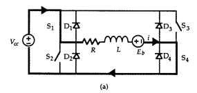
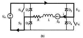
FIGURE 10.76 H-bridge circuit: (a) positive current conduction, and (b) negative current conduction.
Turn-Off Behavior. What takes more work to understand is the turn-off behavior of the H bridge and how phase current is controlled to limit its magnitude. Current control is accomplished by chopping, that is, by employing PWM techniques. Because of its fundamental nature, PWM is discussed at length later. For the time being, consider the turn-off behavior of the H bridge. This behavior is guided by the fundamental behavior of inductors. That is, that current cannot change instantaneously but must be continuous, and the larger the voltage across an inductor, the faster the current through it will change.
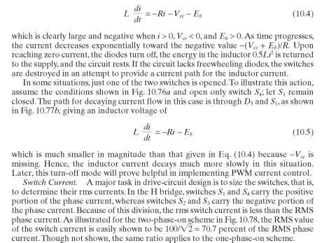
To start, let the phase current be a constant Im with switches S1 and S4 closed, as shown in Fig. 10.76a. Given these initial conditions, consider what happens when both switches are opened to bring the current back to zero. Now, since current no longer flows through S1 and S4, a negative voltage appears across the inductor because di/dt is negative. At the same time, the phase current continues to flow in the same direction because it cannot change instantaneously. The only path for current flow is through diodes D2 and D3, as shown in Fig. 10.77a. No current can flow through diodes D1 or D4. During this time, the voltage across the phase inductance is
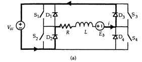
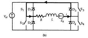
FIGURE 10.77 Current decay in an H-bridge circuit: (a) switches S1 and S4 open, and (b) only switch S4 open.
Summary. Important aspects of the H-bridge circuit include the following:
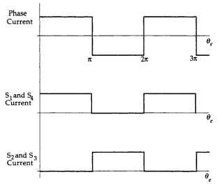
FIGURE 10.78 Phase and switch currents for two-phase-on operation.
• Bidirectional current flow is easily achieved.
^ Given that the back-emf and current have the same sign in Figs. 10.73 and 10.74, the back-emf acts to fight the increase in phase current amplitude during turn-on.
^ In the one-phase-on drive scheme in Fig. 10.73, the back-emf and current have the same sign at the turn-off points.Thus, by Eq. (10.4), the back-emf acts to assist the decrease in phase current during turn-off.
• In the two-phase-on drive scheme in Fig. 10.74, the back-emf and current have opposite signs immediately after the turn-off points. Thus, the back-emf acts to fight the decrease in phase current during turn-off. Thus, the back-emf hinders commutation at both turn-on and turn-off in the two-phase-on drive scheme.
^ At no time can vertical pairs of switches (i.e., S1 and S2 or S3 and S4) be closed simultaneously. If this happens, a shoot-through fault occurs where the motor supply is shorted. In implementation, a short delay is often added between commutations to guarantee that no shoot-through condition occurs.
^ For the square-wave back-emf schemes, the rms switch current is equal to 70.7 percent of the RMS phase current.
• For two-phase motors, H bridges are required, giving a total of eight switches to be implemented by power electronic devices.
Two-Phase Motors (Electric Motors)
Next post: Three-Phase Motors (Electric Motors)
Previous post: BRUSHLESS DC MOTOR DRIVE SCHEMES (Electric Motors)
