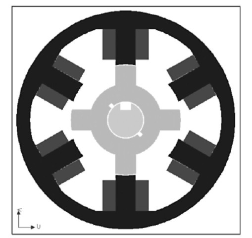
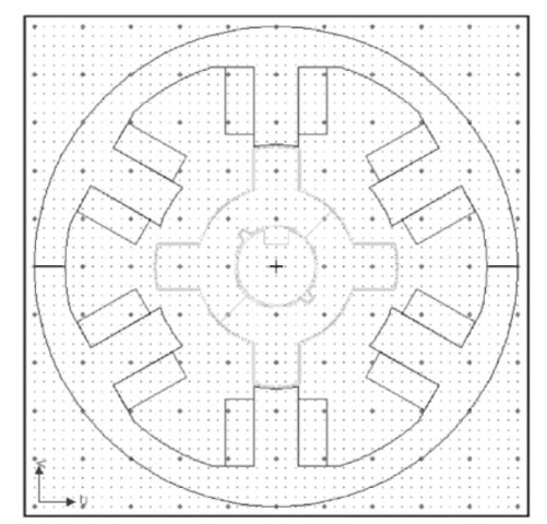
Switched reluctance machines (SRMs) have salient stator and rotor poles with concentrated windings on the stator and no winding on the rotor. The stator windings can be wound externally and then slid onto the stator poles. This provides for a very simple manufacturing process, thus the cost of the machine is also low. The SRM has a single rotor construction, essentially made of stacks of iron, and does not carry any coils or magnets. This feature gives it a rugged structure and provides the machine with the advantage that it can be used at high speeds and better withstand high temperatures. The SRM achieves high torque levels at low peak currents by using small air gaps. Figures 9.1 and 9.2 show a cross-sectional views of a typical 6/4 SRM with six stator and four rotor poles.
The choice of the number of poles to be used in the SRM is important due to the vibration that is produced. A structure such as 12/8 (12 stator and eight rotor poles) provides lower mechanical vibration compared to the 6/4 structure. SRM machines are well

FIGURE 9.1 Cross section of a typical 6/4 SRM with six stator and four rotor poles.
suited for high-speed operations and tend to have higher efficiency at high speeds. They provide constant power over a wide speed range and are highly dynamic with speed. In fact, switched reluctance motor drives are inherently adjustable- or variable-speed drives.
The SRM is a highly reliable machine as it can function even under faulty conditions with reduced performance. One of the reasons for this is that the rotor does not have any excitation source and thus does not generate power into the faulted phase; therefore, no drag torque would be produced under the motoring mode and there are no sparking/fire hazards due to excessive fault currents. In addition, the machine windings are both physically and electromagnetically isolated from one another, reducing the possibility of phase-to-phase faults. The classic SRM drive as a system with converter involves two switches and a winding in series. Thus, even in a case of both switches being turned on at the same time, no

FIGURE 9.2 Cross sectional view of a typical 6/4 SRM with six stator and four rotor poles.
shoot-through faults would occur, unlike the case of AC drives, which lead to shorting of the DC bus.
Switched reluctance machines by a nonsinusoidal voltage waveform, thus resulting in a high torque ripple. This also leads to high noise levels. As per the standards, to have torque ripples of less than 15% in nonsinusoidal excited machines, the number of phases in the SRM has to be increased, which would reflect on the system cost due to the increased number of parts, in this case the switches. A better solution is to use advanced control techniques to reduce the torque ripple and noise. The SRM converters have very high efficiency at low and high speeds. During generation, the efficiency values are remarkably high—above 90%—over a wide speed range.
Electromagnetic torque in the SRM is produced by the tendency of the salient rotor poles to align with the excited stator poles and attain the least reluctance position. The torque developed
depends on the relative position of the phase current with respect to the inductance profile. If the current falls on the negative slope of the inductance profile, then the machine is in the generating mode. The back EMF developed depends on the magnetic parameters of the machine, rotor position, and the geometry of
the SRM.
The current waveforms for the motoring mode and the generating modes are mirror images of each other. During generation, initial excitation has to be provided from an external source, it being a single excited structure. The stator coils are turned on around the aligned position and then turned off before unalignment for generating electricity. The turn-on and turn-off angles as well as the current determine the performance of the machine. During the high-speed motoring mode, the peak value of the current depends on the turn-on time. These timings greatly help in designing optimal and protective control. In addition, in SRM, by changing the turn-on and turn-off angles, the system may be optimized to operate under maximum efficiency, minimum torque ripple, or minimum ripple DC link current. The extended constant power/speed ratio capability of the SRM enables less power requirement during the motoring mode.
The SRM can be current controlled for both motoring and generating modes of operation. During motoring the current is controlled by adjusting the firing angles and applying the current during the magnetization period. If during the current control there is overlapping of the phase currents, it leads to an increase in the maximum torque level. During the generation mode of operation, the torque must be fed to the machine when the inductance level is reducing, i.e., when the rotor is moving from the aligned position to the unaligned position.
