4.2.4
The geometry of the stator lamination requires breaking it down into several small areas in the same manner as used for the armature.
Using Figs. 4.56,4.57, and 4.58 and the XY coordinate system as shown, this subsection uses the given dimensions to determine the field slot area.
The following dimensions are needed from the lamination drawing. Some manufacturers distribute drawings with only a few dimensions on them, but will give these detailed drawings if requested.
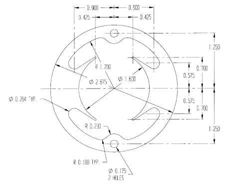
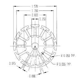
FIGURE 4.56 Example of a lamination drawing.
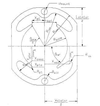
FIGURE 4.57 Stator (field) lamination.
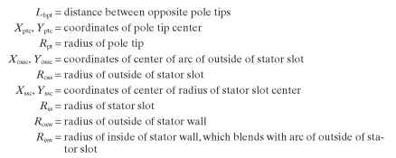
Depending on which stator dimension is given, the X coordinate for the center of the pole tip, in inches, is

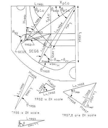
FIGURE 4.58 Stator (field) slot area.
The pole arc angle is twice the angle from the center of the lamination to the tip of the pole closest to the other pole. The pole arc angle, in degrees, is
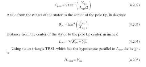
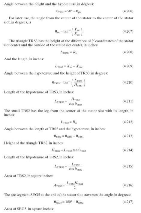
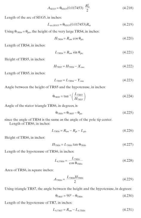
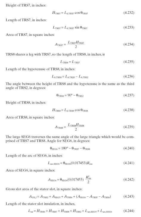
The net slot area available for the field winding on one pole is the GSA minus the area of the insulation, in square inches:
![]()
Constants for Stator Reactance Calculations. As with the armature, the geometry of the stator slot must be known in order to calculate the reactance. Note that the field slot can be turned to resemble the armature slot. Use Figs. 4.58 and 4.59 to determine the following values which will be needed later.
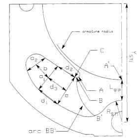
FIGURE 4.59 Dimensions for stator reactance.
The values of a and b, as similar to the armature, in inches:


There is no c dimension as in the armature slot dimensions.
Length of the interpolar air gap, which is the distance between the armature and the stator yoke at their closest position, in inches:
![]()
where YST1 is the Y coordinate of the center of radius RST1.
The points on the pole tip A, B, and C are used as the starting points of three arcs which are drawn with the edge of the armature as the center. These arcs were derived from flux mapping using curvilinear squares, which will not be discussed here. C is the point where line e intersects the pole. A is the point where the radius of the pole tip would be parallel to the armature tooth tip. B is the point on the slot side of the pole tip which is halfway between A and C. The point B’ is the point that the average leakage flux would travel to on the stator yoke.
Arc length BW is the length of the arc of radius RBW (which is the distance from A to B) shortened by the radius RST1. Arc length AC is the arc around the pole tip of about 90°.

Field (Stator) (Electric Motors)
Next post: Magnetic Paths in the Field (Stator) (Electric Motors)
Previous post: Armature Conductors (Electric Motors)
