9.9
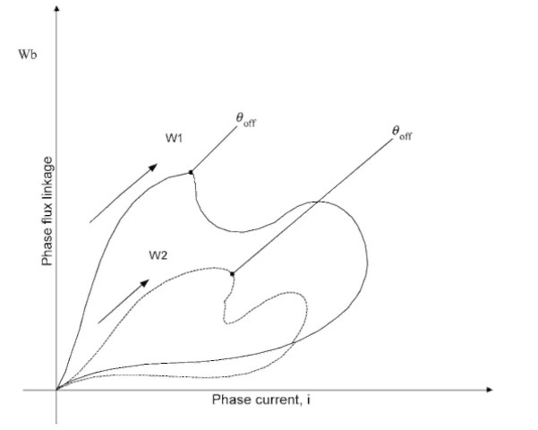
Two energy conversion cycles for an SRG at two different speeds are shown in Fig. 9.59 The area enclosed by the loop corresponds to the energy converted from mechanical to electrical form for the two cases. The dot in Figure 9.59 indicates the point where the control-lable

FIGURE 9.59 Energy conversion cycle.
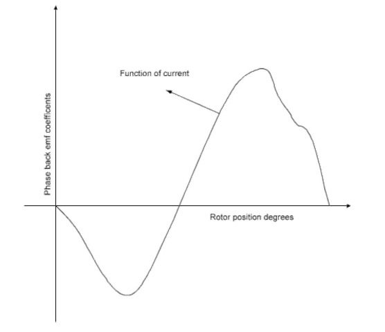
switches are turned off and phase current is supported by diodes. Figure 9.60 gives the back EMF coefficient for the given value of the phase current. The back EMF coefficient is negative during the region of decreasing phase inductance and positive during the region of increasing phase inductance. For a certain level of the current value, the peak back EMF coefficient increases, but for any further increase in phase current, the back EMF coefficient decreases.
During excitation prior to the aligned position, phase current increases with back EMF, reducing effectiveness of the source voltage. This requires significant advancement in turn-on angle to have adequate phase current as the rotor enters the region of decreasing phase inductance. During demagnetization, phase current decreases if the source voltage is larger in magnitude than the

FIGURE 9.60 Phase back EMF coefficient vs. rotor position.
back EMF. At low-speed operation, multiple periods of excitations are required so that current is regulated to maintain adequate excitation as the rotor moves from the aligned position to the unaligned position. At high-speed operation, when switches are turned off, phase current increases first in the face of the negative source voltage and decreasing flux linkage.
ENERGY CONVERSION CYCLE (Electric Motor)
Next post: Utility Interface Issues (Electric Motor)
Previous post: GENERATIVE MODE OF OPERATION (Electric Motor)
