3.2
The basic purpose of an end frame, sometimes denoted an end bell, end shield, or bracket, is to contain the shaft bearings and support the rotor assembly. It will also act as a heat transfer device. On open motors, the end frame will have slots for air to pass. On enclosed motors, the end frames will be solid, with no openings. A variety of end frames are shown in Figs. 3.13, 3.14, and 3.15.
Like housings, end frames come in cast-iron, steel, zinc, or aluminum castings.
Cast-iron castings are usually found on motors of 3 hp and larger. The service application is in the industrial market where severe conditions may exist. Materials are usually of about 30,000 lb/in2 tensile strength and are free machining.The typical sequence of operations is a two-machine cell—a computer numerically controlled (CNC) machine prepares the bearing bore and end frame diameter, and a manual drill is used to prepare the holes for the housing attachment.
The steel material is usually SAE 1010 to 1020. This type of end frame may be found on all types and sizes of motors. A coil is processed through a stamping press, and each part is drawn into form as a stamping. This is usually a progressive die operation.
A self-aligning bearing is installed and lubricant is applied. Then the bearing is sized for the only machining process.
Zinc or aluminum end frames are found on most motor types and sizes and generally are castings. End frames are usually cast in a horizontal die caster. Because of its density, zinc is usually limited to end frames for motors 3 in in diameter or less. If the parts are small enough, more than one part is made at one time. This depends on the part and machine sizes. Also, on motors above M hp, a steel bearing insert is usually die cast in the part. Following the die casting and part cooling, the part is trimmed. Many manufacturers have installed robots for this operation because of the heat and environmental conditions.
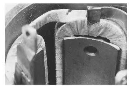
FIGURE 3.7 Solid steel pole piece.

FIGURE 3.8 Frame and field assembly.
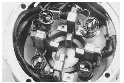
FIGURE 3.9 Brush assembly.
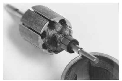
FIGURE 3.10 Winding a commutator.
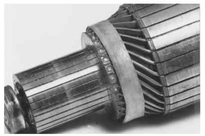
FIGURE 3.11 Core and shaft assembly.
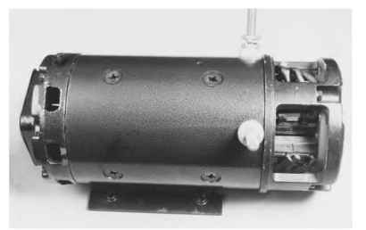
FIGURE 3.12 Complete motor.
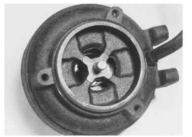
FIGURE 3.13 End frame.
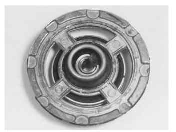
FIGURE 3.14 End frame.
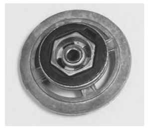
FIGURE 3.15 End frame.
The bearing bore and housing end frame diameter of the end frame are then machined. This is done on either a CNC lathe or a special automatic machine, depending on size and volume.
Some very small motors use an oil-soaked wick, as seen in Fig. 3.14, for lubrication. This is inserted after machining.
