2.5
Efficiency is defined as the ratio of the output power to the input power to the motor expressed in percent; thus,
![tmpA3-14_thumb[3] tmpA3-14_thumb[3]](http://lh4.ggpht.com/_X6JnoL0U4BY/S1ftxDLU84I/AAAAAAAAHOY/XHZBHv_8hs4/tmpA314_thumb3_thumb.jpg?imgmax=800)
TABLE 2.4b Full-Load Nominal Efficiencies of Three-Phase Four-Pole Energy-Efficient TEFC Motors
| Nominal efficiency range | Average nominal efficiency | ||
| hp | Min. | Max. | |
| 1 | 77.0 | 85.5 | S2.5 |
| 2 | 82.5 | 86.5 | 84.2 |
| 3 | 82.5 | 89.5 | 87.8 |
| 5 | 85.5 | 90.2 | 88.4 |
| 7.5 | 87.5 | 91.0 | 90.3 |
| 10 | 89.5 | 91.7 | 90.6 |
| L5 | 91.0 | 92.5 | 92.0 |
| 20 | 91.9 | 93.0 | 92.6 |
| 25 | 92.3 | 94.1 | 93.1 |
| 30 | 92.6 | 94.1 | 93.4 |
| 10 | 93.1 | 94.5 | 93.8 |
| 50 | 93.2 | 95.0 | 94.0 |
| 60 | 93.6 | 95.0 | 94.4 |
| 75 | 93.8 | 95.4 | 94.7 |
| 100 | 94.1 | 95.4 | 94.9 |
| 125 | 94.2 | 95.8 | 95.2 |
| 150 | 94.2 | 96.2 | 95.4 |
| 200 | 95.2 | 96.2 | 95.7 |
aBased on available published data. It may also be expressed as
![tmpA3-15_thumb[3] tmpA3-15_thumb[3]](http://lh3.ggpht.com/_X6JnoL0U4BY/S1fty6T013I/AAAAAAAAHOg/fC84rMHM9Rw/tmpA315_thumb3_thumb.jpg?imgmax=800)
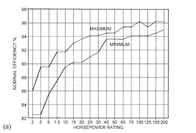
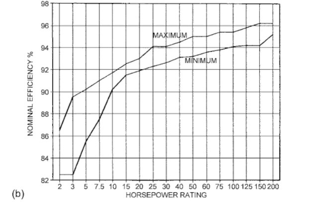
FIGURE 2.5 (a) Range of nominal efficiency for current industry energy-efficient open 1800-rpm induction motors. (b) Range of nominal efficiency for current industry energy-efficient TEFC 1800-rpm induction motors.
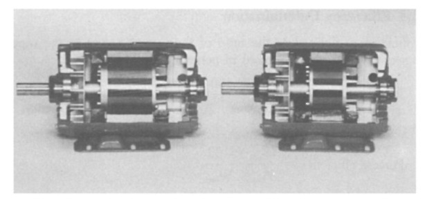
FIGURE 2.6 Comparisons of energy-efficient and standard motors. (Courtesy of MAGNETEK, St. Louis, MO.)
where
Ws = stator winding loss
W, = rotor winding loss, slip loss
Wc = magnetic core loss
= no-load friction and windage loss Ws; = full-load stray load loss
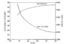
FIGURE 2.7 Loss reduction and efficiency improvement trend for 50-hp, 1800-rpm induction motor.
The accuracy of the efficiency determination depends on the test method used and the accuracy of the losses determined by the test method. There is no single standard method used throughout the industry. The most commonly referred to test methods are the following: IEEE Standard 112-1984 Standard Test Procedure for Polyphase Induction Motors and Generators; International Electrotechnical Commission (IEC) Publication 34-2, Methods of Determining Losses and Efficiency of Rotating Electrical Machinery from Tests; and Japanese Electrotechnical Commission (JEC) Standard 37 (1961), Standard for Induction Machines.
Each of these standards allows for more than one method of determining motor efficiency, and these can be grouped into two broad categories: direct measurement methods and segregated loss methods. In the direct measurement methods, both the input power and output power to the motor are measured directly. In the segregated loss methods, one or both are not measured directly. With direct measurement methods.
![tmpA3-20_thumb[1] tmpA3-20_thumb[1]](http://lh6.ggpht.com/_X6JnoL0U4BY/S1fvLdflSeI/AAAAAAAAHPI/zGJQ4W8lF0s/tmpA320_thumb1_thumb2.jpg?imgmax=800)
2.5.1
IEEE Standard 112-1984
Methods A, B, and C are direct measurement methods:
Method A: Brake. In this method, a mechanical brake is used to load the motor, and the output power is dissipated in the mechanical brake. The brake’s ability to dissipate this power limits this method
primarily to smaller sizes of induction motors (generally fractional horsepower).
Method B:
Dynamometer. In this method, the energy from the motor is transferred to a rotating machine (dynamometer), which acts as a generator to dissipate the power into a load bank. The dynamometer is mounted on a load scale, a strain gauge, or a torque table. This is a very flexible and accurate test method for motors in the range 1500 hp. However, to ensure accuracy, dynamometer corrections should be made as outlined in the test procedure. Method B includes a procedure for the stray load loss data smoothing by linear regression analysis. These smoothed values of stray load loss are used to calculate the final value of efficiency.
Method C:
Duplicate Machines. This method uses two identical motors mechanically coupled together and electrically connected to two sources of power, the frequency of one being adjustable.* Readings are taken on both machines, and computations are made to calculate efficiency. This procedure includes a method of determining the stray load losses.
Methods E and F are segregated loss methods:
Method E: Input Measurements.f The motor output power is determined by subtracting the losses from the measure motor input power at different load points. For each load, the measured I2R losses are adjusted for temperature and added to the no-load losses of friction, windage, and core. The stray load loss, which may be determined either directly, indirectly, or by the use of an agreed-on standardized value, is included in this total.
Method F: Equivalent Circuit Calculations. When load tests cannot be made, operating characteristics can be calculated from no-load and impedance data by means of an equivalent circuit. This equivalent circuit is shown in Fig. 2.8. Because of the nonlinear nature
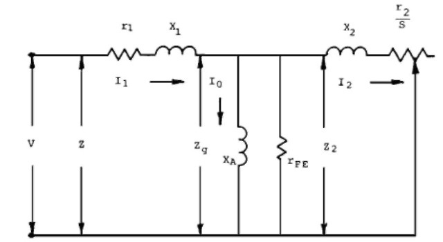
FIGURE 2.8 Polyphase induction motor per phase equivalent circuit. (From R. E. Osterlei, Proceedings of the 7th National Conference on Power Transmission, Gould Inc., St. Louis, MO, 1980.)
of these circuit parameters, they must be determined with great care to ensure accurate results. Procedures for determining these parameters are outlined in the standard as determined by a separate test. Accurate predictions of the motor characteristics depend on how closely r2 represents the actual rotor resistance at low frequency.
2.5.2
IEC Publication 34-2
The same basic alternate methods as those outlined for IEEE 112 are also allowed for in IEC 34-2. However, a preference is expressed for the summation of losses method for the determination of motor efficiency. This is similar to IEEE 112 methods E and F except that the IEC method specifies stray load loss and temperature corrections differently. The IEC stray load losses are assumed to be 0.5% of rated input, whereas the IEEE standard states a preference for direct measurement of the stray load losses. The resistance temperature corrections in the IEC method are given as fixed values depending on insulation class, whereas the IEEE standard recommends use of the measured temperature rise for correcting resistance. These differences generally result in higher motor efficiency values by the IEC method.
2.5.3
JEC Standard 37
The JEC 37 standard also specifies the same basic methods as IEEE 112 with the exception of method C, duplicate machines. The preferred method for determining efficiency in this standard utilizes circle diagrams. This is a graphical solution of the T equivalent circuit of the induction motor. (This is similar to IEEE method F with the R circuit branch.) As in the IEC standard, different methods are usfeed to determine the circuit parameters and adjust the performance calculations. Principal among these is setting stray load loss equal to zero and using fixed values for resistance temperature corrections, which are a function of insulation class. These differences generally produce higher values for motor efficiency than the IEEE methods.
2.5.4
Comparison of Efficiencies Determined by Preferred Methods
To illustrate the variations in efficiency resulting from the use of the preferred methods, the full-load efficiency of several different polyphase motors was calculated by the preferred test methods given in the three standards. The results are shown in Table 2.5. As the values show, the efficiencies determined by the IEC and JEC methods are higher than the IEEE method. The major reason for this difference is the way in which stray load losses are accounted for. The IEEE method B stray load losses are included in the direct input and output measurements, whereas in the IEC method the stray load losses are
TABLE 2.5 Efficiency Determined by Preferred Methods
| JEC 37, circle | IEC 34-2 loss | IEEE 112, | |
| hp | diagram | summation | method B |
| 5 | 88.8 | 88.3 | 86.2 |
| 10 | 89.7 | 89,2 | 86.9 |
| 20 | 91.9 | 91.4 | 90.4 |
| 75 | 93.1 | 92.7 | flO.O |
taken as 0.5% of the input, and in the JEC method they are set equal to zero. This comparison shows how important it is to know the method used to determine efficiency when comparing electric motor performance from different sources and countries.
2.5.5
Testing Variance
In addition to variance in efficiency due to test methods used, variances can also be caused by human error and test equipment accuracy. With dynamometer (IEEE 112, method B) testing, as with all test methods, there are several potential sources of inaccuracies: instrument accuracy, dynamometer accuracy, and instrument and dynamometer calibration. Therefore, to minimize these test errors, it is recommended that all the equipment and instruments be calibrated on a regular basis.
With proper calibration, dynamometer testing provides consistent and verifiable electric motor performance comparison. NEMA conducted a round-robin test of three different horsepower ratings (5, 25, and 100 hp) with a number of electric motor manufacturers. After a preliminary round of testing, each manufacturer was requested to test the motors in accordance with IEEE 112, method B, both with and without mathematical smoothing of the stray load loss. The results of these tests are summarized in Table 2.6.
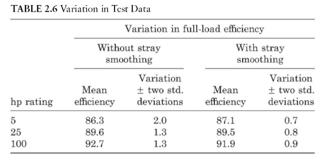
Based on the test results, NEMA adopted a standard test procedure for polyphase motors rated 1-125 hp in accordance with IEEE Standard 112, method B, including mathematical smoothing of the stray load loss. It is recommended that this method of determining motor efficiency be used wherever possible.
