8.3
The permanent magnet BLDC motor shares the same torque-speed characteristics and the basic operating principles of the brushed DC

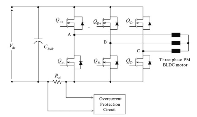
FIGURE 8.14 Three-phase MOSFET inverter.
motor. The main difference is that the field windings are replaced by permanent magnets and the commutation is done electronically. Using permanent magnets and eliminating the brushes offers many distinctive advantages, such as high performance torque control, low torque ripples, long life, high power-to-weight ratio, low noise and low electromagnetic interference, better heat dissipation, low maintenance, and very high speed of operation.
The power electronic driver for the BLDC motor can be an IGBT-based inverter, as shown in Figs. 8.7 and 8.8. It can also be a MOSFET-based inverter as shown in Fig. 8.14. An IGBT-based driver is usually used for high-power or high-voltage applications.
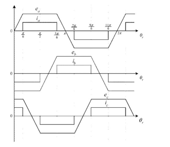
Figure 8.15 shows the three-phase voltage and current waveforms for a trapezoidal back EMF BLDC machine. In order to maintain the current as shown in Fig. 8.15, a hysteresis (bang-bang) control technique can be used. With the hysteresis control, the current is directly controlled; therefore, output torque of the

FIGURE 8.15 Ideal back EMF and phase current waveforms of the BLDC motor.

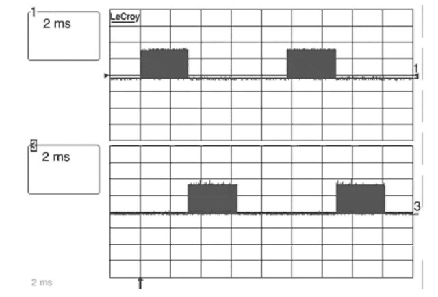
FIGURE 8.16 Driving pulses for QA_ and QB_ of inverter in Fig. 8.14, 10 V/div.

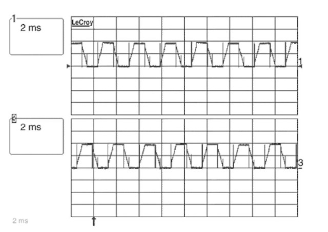
FIGURE 8.17 Voltages of phase A and phase B of the driver shown in Fig. 8.14.
motor is controlled. However, the switching frequency is variable. In order to have a constant switching frequency, a pulse width modulation technique can be used. There are many integrated circuits (ICs) available in the market that use PWM techniques. The advantage is that the average of the applied voltage to the motor terminals is directly controlled. Therefore, speed of the motor is directly controlled by changing the duty cycle of the PWM switching scheme. Simplicity is another advantage of the PWM methods.
In Fig. 8.14, for overcurrent protection, sense resistance Rsi is used. The sense voltage over Rsi, which is proportional to the load current, is fed into a comparator on the main control board. The overcurrent circuit limits the motor current. Driving pulses and phase voltages for the inverter in Fig. 8.14 are given in Figs. 8.16 and 8.17, respectively.
BLDC POWER ELECTRONIC DRRIVES (Electric Motor)
Next post: SENSORLESS TECHNIQUES FOR BLDC MOTOR DRIVES (Electric Motor)
Previous post: MODELING (Electric Motor)
