8.1
Permanent magnet (PM) BLDC machines can be classified according to the type of the permanent magnet (ferrite, ceramic, alnico, or
rare earth), the shape of the back EMF waveform (trapezoidal or sinusoidal), the mounting of the permanent magnet (surface mounted or interior-mounted), the direction of the magnetic flux (radial or axial), the configuration of the windings (slot windings or slotless surface windings), or the power electronic drive (unipolar drive or bipolar drive).
Permanent magnet BLDC motors are classified as surface-mounted permanent magnet (SMPM) or interior-mounted permanent magnet (IPM) types. Figure 8.3 shows these two configurations. In the case of the surface-mounted permanent magnet machine, the magnets are mounted on the surface of the rotor, while for the interior-mounted permanent magnet machine, the magnets are inside the rotor. In the surface-mounted machine, the air gap might be nonuniform, while for the interior mounted machine, the air gap is uniform.
The stator shape of the PM BLDC motors can be configured with slots (slotted type) or without slots (slotless type); the slotless
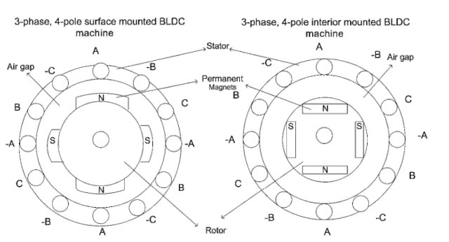
FIGURE 8.3 Surface-mounted and interior-mounted BLDC machines.
windings are also called surface winding or air gap winding. There is a special trend to use slotless BLDC motors especially in low-power and high-speed, high-performance applications. A method to eliminate the cogging torque in BLDC machines is to eliminate its source: the reluctance changes in the magnetic circuit during the rotation of the PM around the stator. In a traditional brushless motor, copper wires are wound through slots in a laminated steel core. As magnets pass by the lamination shoes, they have a greater attraction to the iron at the top of the laminations than to the air gap between shoes. This uneven magnetic pull causes cogging, which in turn increases motor vibrations and noise. Therefore, the key to smooth brushless performance centers on a slotless stator. Additionally, a slotless design significantly reduces damping losses.
Figure 8.4 shows the permanent magnet rotor of a three-phase, 1-hp BLDC motor; Fig. 8.5 shows the stator of a three-phase, 1-hp BLDC motor; and Fig. 8.6 shows the rotor and stator of a three-phase, 1-hp BLDC motor.
The BLDC motor consists of a stator, which contains the stator windings, and a rotor, on which permanent magnets are mounted. These magnets supply the field flux. The classic converter for the
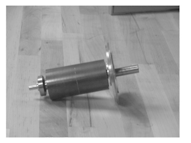
FIGURE 8.4 Permanent magnet rotor of a three-phase, 1-hp BLDC motor.
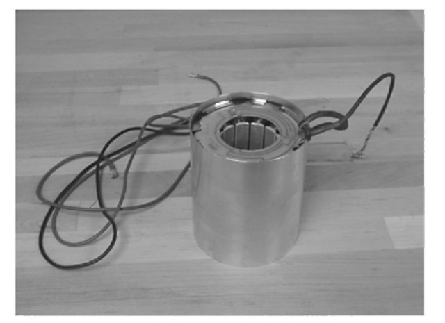
FIGURE 8.5 Stator of a three-phase, 1-hp BLDC motor.
BLDC motor is nothing but a DC/AC three-phase inverter, as shown in Fig. 8.7. The DC link voltage can be obtained from a pulse width modulation (PWM) rectifier from the AC supply, as shown in Fig. 8.8. A simple diode bridge can also be used.
To switch the coils in the correct sequence and at the correct time, the position of the rotor field magnets must be known. For
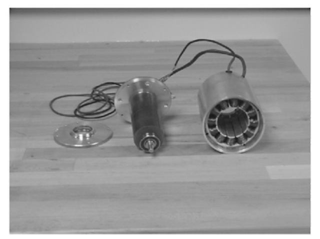
FIGURE 8.6 Rotor and stator of a three-phase, 1-hp BLDC motor.
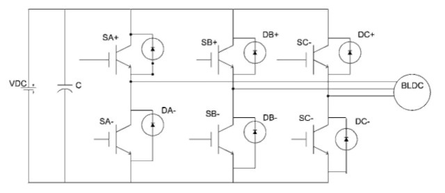
FIGURE 8.7 Classic BLDC power electronic driver.
locating the rotor field magnets, an absolute sensing system is required. An absolute sensing system may consist of Hall sensors or optical encoders.
The function of the controller is to switch the right currents in the right stator coils at the right time in the right sequence by taking the information supplied by the sensor and processing it with preprogrammed commands to make the motor perform as desired.
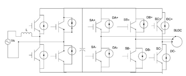
FIGURE 8.8 A typical BLDC driver with a PWM rectifier at its front end.
BLDC MACHINE CONFIGURATIONS (Electric Motor)
Next post: MODELING (Electric Motor)
Previous post: Brushless DC Motor Drives (Electric Motor)
