ABSTRACT
This paper presents our on-going efforts on development and characterization of transparent Interpenetrating Polymer Networks (t-IPNs) with polyurethane (PU) and poly(methyl methacrylate) (PMMA) as constituents. The resulting molecular composite is a fully cross-linked IPN with PU as the tough phase and PMMA as the stiff phase. By varying the volume fraction of the stiff and tough phases, t-IPNs with PMMA/PU content in the range of 90%/10% to 70%/30% have been prepared. Reaction kinetics and process parameters are carefully controlled to avoid phase separation to achieve optical transparency in the resulting IPN. Tensile tests show that a significant failure strain enhancement can be achieved but with a loss of stiffness relative to PMMA. Preliminary fracture tests show that an optimum PMMA/PU ratio in the IPN can produce enhancement in fracture toughness relative to PMMA.
Keywords: Transparent interpenetrating polymer networks (t-IPNs); Polyurethane; Poly(methyl methacrylate); Tensile strength; Quasi-static fracture; Fracture toughness
Introduction
Tough, lightweight and optically transparent polymers are desirable in many civil and military applications as hurricane resistant windows, protective goggles, aircraft canopies, automotive windows, sound and vibration damping materials to name a few. Interpenetrating polymer networks (IPNs) are a relatively new class of materials suitable for these kinds of applications. IPNs are molecular composites where one polymer is synthesized and/or crosslinked in the immediate presence of the other(s) [1]. Over the years several investigators have attempted to develop such materials [2-10]. However, most have resulted in opaque and/or translucent IPNs and very limited work exists from the perspective of transparent IPNs for the aforementioned applications. Furthermore, the reported ones mostly do not address IPN material characterization in terms of mechanical and fracture behavior.
The present work aims at development and characterization of a novel lightweight, tough and transparent interpenetrating polymer network (t-IPN) materials by combining stiff and compliant polymer phases where each polymer forms its own network and the networks interpenetrate other during polymerization. In this work, poly(methyl methacrylate) (PMMA) is used as stiff/hard phase whereas polyurethane (PU) is employed as compliant/soft phase. Depending upon the ratio of soft and hard phases, the mechanical and fracture properties of the resultant IPNs can be tailored for a given application. The hard phase obtained from the PMMA network imparts higher strength, while the soft phase formed by PU network provides ductility and crack growth as well as impact resistance to resultant t-IPN systems. In this study, the mechanical and fracture responses of t-IPNs with varying PMMA/PU ratios ranging from 90/10 to 70/30 were studied by performing a series of tensile and fracture tests under quasi-static loading conditions.
Material Preparation
The reagents used for the PMMA system were: methyl methacrylate (MMA, 99%, ACROS Organics), trimethylolpropane trimethacrylate (TRIM, Sigma-Aldrich) and 2,2′-Azobisisobutyronitrile (AIBN, 98%, Sigma-Aldrich), and the reagents used for the PU system were: poly(tetramethylene ether)glycol (PTMG), 2-Ethyl-2-(hydroxymethyl)-1,3-propanediol (TRIOL, 98%, ACROS Organics), 1,6 diisocyanatohexane (DCH, 99+%, ACROS Organics) and dibutyltin dilaurate (DBTDL, 98%, Pfaltz and Bauer, Inc.). The five different compositions (PMMA/PU ratio) of /-IPNs were prepared, namely 90/10, 85/15, 80/20, 75/25 and 70/30.
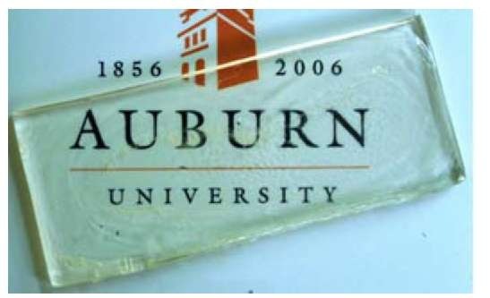
Fig. 1. A f-IPN (80/20, PMMA/PU) sheet (Dimensions: 170 x 80 x 8 mm3).
A typical experimental protocol was determined to prepare /-IPNs of desired PMMA/PU ratios. In this protocol, a homogeneous mixture was prepared at room temperature by dissolving the required amounts of PTMG, TRIOL and DCH in the methacrylic monomer MMA and cross-linker TRIM under vigorous stirring for about 10 minutes. Next, the free-radical initiator, AIBN was dissolved during mixing and finally the desired amount of DBTDL (catalyst) was added followed by further stirring of the mixture for another 5 minutes. This homogeneous mixture was then poured into a closed mold made of poly(tetrafluro ethylene) (Teflon) sheet. Enough care was exercised to avoid any possible evaporation of PMMA from the mixture by sealing the mold interfaces with a thin layer of caulk. The mold containing the PMMA/PU mixture was kept in an oven at 60°C for 24 hours followed by further curing at 80°C for another 24 hours. After curing, the mold was left in the oven at room temperature for another 12 hours for complete cooling of the casting. It should be noted that, slow cooling from 80°C to room temperature in the oven prevents warpage of the cured sheet and minimizes residual stresses. A completely transparent 80/20 (PMMA/PU) /-IPN sheet of dimensions 170 mm x 80 mm x 8 mm is shown in Fig. 1.
Experimental and Testing Procedure
The uniaxial quasi-static tensile tests were carried out in an Instron universal testing machine to measure properties such as elastic modulus, tensile strength, percent elongation at break. Dogbone-shaped specimens were prepared from /-IPN sheets of thickness 4 mm according to ASTM D638 test method [11]. All the experiments were conducted at room temperature under displacement controlled conditions at a constant crosshead speed of 2 mm/min. Typically 3 specimens were tested at the same crosshead speed for each /-IPN category.
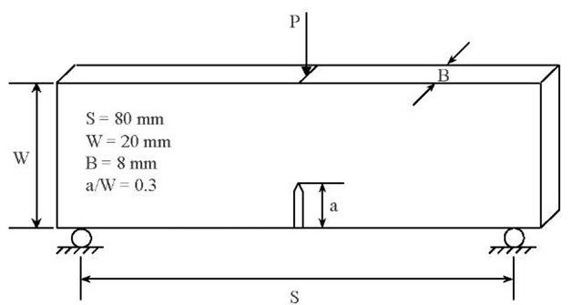
In order to characterize toughness of /-IPNs in terms of the critical-stress-intensity factor, KIc, quasi-static fracture tests were performed in accordance with ASTM D5045 test method [12]. For quasi-static fracture tests, the cured /-IPN sheets were machined into rectangular coupons of dimensions 80 mm x 20 mm x 8 mm. An edge notch of 6 mm in length was cut into the samples and the notch tip was sharpened using a razor blade. The three-point bend specimen geometry and loading configuration can be seen in Fig. 2. The single edge notched bend, SENB, specimens were loaded in displacement control mode with testing speed of 0.25 mm/min. The load vs. deflection data was recorded up to crack initiation and during stable crack growth, if any, and the crack initiation toughness, KIc was calculated using the load (P) at crack initiation. Again, for each /-IPN category at least three sets of experiments were performed at laboratory conditions.
Fig. 2. Three-point bend specimen (SENB) geometry and loading configuration for quasi-static fracture tests.
The mode-I stress intensity factor for a single edge notched bend (SENB) specimen loaded in three-point bending using the linear elastic fracture mechanics is given by [13],
Experimental Results
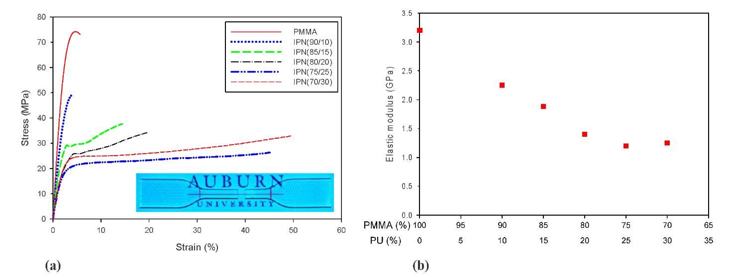
The mechanical properties of t-IPNs obtained from quasi-static tensile tests are shown in Figs. 3 and 4. A set of representative stress-strain curves for neat PMMA and various t-IPN specimens can be seen in Fig. 3(a). The initial response in each case depicts linear elastic region with only a modest nonlinearity in the case of neat PMMA and 90/10 t-IPN before failure compared to the other cases showing large nonlinear responses. The t-IPN specimens 85/15 and 80/20 show yielding at ~30 and ~26 MPa respectively followed by some strain hardening before failure. In the case of 75/25 and 70/30 cases, a yield plateau can be seen between ~4 to 20% strain followed by appreciable strain hardening region until ultimate failure. The elastic modulus for each specimen was deterimined by constructing a tangent to the initial part of the stress-strain curves and the variation of elastic modulus as a function of relative pecentanges of PMMA and PU is shown in Fig. 3(b). It can be seen that there is a reduction in Young’s modulus as the PU content increases in the t-IPNs.
Fig. 3. (a) Typical stress-strain response for MPNs, (b) Elastic modulus variation as a function of PMMA-PU percenatge.
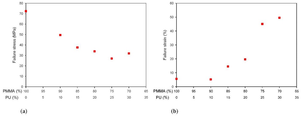
The ultimate stresses and failure strains for each material are plotted against the relative percentages of PMMA and PU in Figs. 4(a) and (b) respectively. Similar to elastic modulus, a decreasing trend in ultimate stress can be seen in Fig. 4(a) as the percentage of PU increases in the t-IPN. Fig. 4(b) depicts variation of percent elongation at break and as expected the failure strain increases with increasing proportions of PU in the PMMA network.
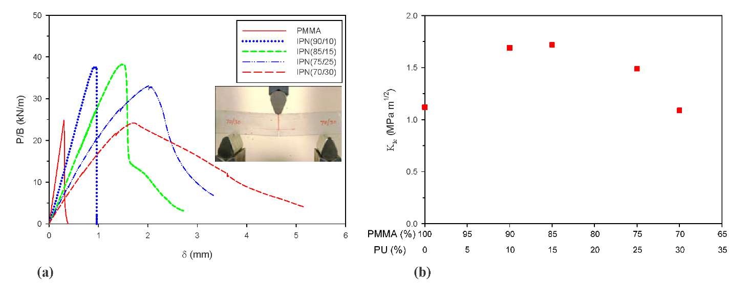
The quasi-static fracture tests results for t-IPNs are shown in Fig. 5. The normalized load-deflection curves for each specimen are shown in Fig. 5(a). It can be seen that the curves are generally linear in the initial stage of deformation for each specimen. The neat PMMA and 90/10 t-IPN show complete linear region upto peak load followed by a sudden drop in the load, signalling crack initiation. However, in the case of other specimens, as the applied load increases, the specimens start to respond nonlinealry before reaching the peak load, and again the extent of nonlinearity increases with increasing PU content. This nonlinearity in the pre-peak load region is attributed to crack-tip blunting and crazing before crack initiation. Moreover, propagation of the macro-crack is arrested unless the applied load is increased. Because of this observed mechanism, the crack may deviates from its original propagation plane requiring additional load and energy for further propagation.
Fig. 4. (a) Variation of failure stress for MPNs with changes in PMMA-PU ratios, (b) Variation of strain at failure for /-IPNs with changes in PMMA-PU ratios.
From Fig. 5(a), it can also be seen that at peak load the deflections are more as the PU content increases in /-IPNs. Furthermore, the overall deflection also increases with increasing PU content and the area under these curves represents the strain energy absorbed. Therefore, it is worth noting that the strain energy increases as the amount of PU increases in /-IPNs.
Fig. 5. (a) Normalized load-deflection response for MPNs, (b) Variation of quasi-static fracture toughness for MPNs.
The quasi-static crack initiation toughness, KIc was calculated using the load at fracture in each case and the variation of KIc with changes in PMMA/PU ratios can be seen in Fig. 5(b). A ~60% improvement in static crack initiation toughness is quite evident for /-IPNs when compared to the neat PMMA. Furhter, the trends in KIc values with increasing PU content suggest that there is an optimum PMMA/PU ratio for which the quasi-static fracture toughness is highest. In this work, 90/10 and 85/15 /-IPNs provide maximum fracture toughness among all cases.
Summary
In this study, /ransparen/ Interpenetrating Polymer Networks (/-IPNs) with polyurethane (PU) and poly(methyl methacrylate) (PMMA) as constituents were prepared by varying the volume fraction of stiff and tough phases with PMMA/PU content in the range of 90%/10% to 70%/30%. The /-IPNs were mechanically characterized in terms of tensile strength, elastic modulus, elongation at break and crack initiation toughness by performing a series of quasi-static tensile and fracture tests. The effects of variation of the PMMA/PU ratios on the aforementioned properties were examined. Tensile tests show that there was gradual reduction in elastic modulus and tensile strength with consequent increase in elongation at break relative to neat PMMA. Preliminary quasi-static fracture tests show that an optimum PMMA/PU ratio in the IPN can produce greatly enhanced fracture toughness with respect to neat PMMA.
