Workstation Display Standards
The engineering workstation industry, as previously noted, developed its own de facto standards separately from those of the PC market. As was the case with the PC, there were still no true industry standards, although there was some degree of commonality in the design choices made by the manufacturers of these systems. “Workstation” computers differ from those traditionally considered “PCs” in several ways impacting the display and the display interface options. First, since these are generally more expensive products, they are not under quite as much pressure to minimize costs; more expensive, higher-performance connectors, cabling, etc., are viable options. In addition, the workstation market has traditionally been dominated by the “bundled system” model, in which all parts of the system – the CPU, monitor, keyboard, and all peripherals – are supplied by the same manufacturer, often under a single product number. This makes for a very high “connect rate” (the percentage of systems in which the peripherals used are those made by the same manufacturer as the computer itself) for the display; unique and even proprietary interface designs are not a significant disadvantage in such a market. In fact, it has been very uncommon in the workstation market for two manufacturers to use identical display interfaces. The last difference from the PC industry comes from the operating system choice. Rather than a single, dominant OS used across the industry – as in the case with the various forms of Microsoft’s “Windows” system in the PC market – workstation products have generally used proprietary operating systems, often some version of the Unix OS. Under this model, there is little need for industry-standard display formats or timings, nor are displays or graphics systems required to support the common VGA “boot” modes described earlier. This made for the workstation industry generally using fixed-timing designs, including singlefrequency high-resolution displays. This has only recently changed, as a convergence of the typical workstation display requirements with the high end of the PC market has made it more economical for workstations to use the same displays as the PC. Even when using what are essentially multifrequency “PC” monitors, however, workstation systems commonly remain set to provide a single format and timing throughout normal operation.
In the early-to-mid-1980s, as the workstation industry began to develop physical system configurations similar to those of the PC (a processor or system box separate from the display), the most common video output connectors were BNCs,carrying separate RGB analog video signals. As with the PC, signal amplitude standards were approximately those of RS-343 (0.714 V p-p), again with very little standardization between the various possibilities (0.660, 0.700, and 0.714 V p-p) which might be produced. In a major departure from the typical PC practice, however, many workstation manufacturers chose to use composite sync-on-video, generally supplied on the green signal only (and thus making only this a nominal 1.000 V p-p, including the sync pulses).
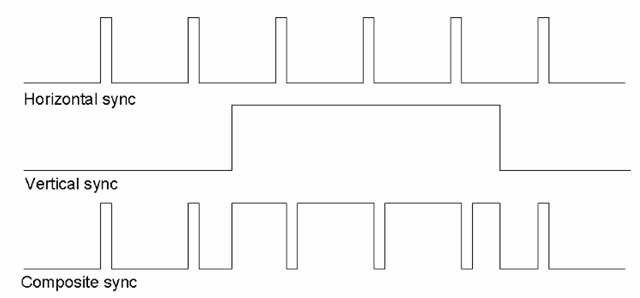
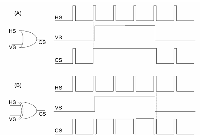
Here again, the computer industry chose to do things somewhat differently from the standard practices established for television. In the television standards, the sync signals are always composited such that horizontal sync pulses are provided during the vertical sync pulse, although inverted from their normal sense (Figure 9-6); such pulses are referred to as serration of the vertical sync pulse. Further, television standards require that the reference edge of the horizontal sync pulse (generally, the trailing edge of this pulse is defined as the point from which all other timing within the line is defined) be maintained at a fixed position in time, regardless of the sense of the pulse. (The effect of this is that the sync pulse itself shifts by its own width between the “normal” version, and the “inverted” pulses occurring during the vertical sync interval.) In those computer display systems that used composite sync, either as a separate signal or provided on the green video, this requirement has only rarely been met. Most often, computer display systems produce composite sync either by simply performing a logical OR of the separate horizontal and vertical sync signals, or (in a slightly more sophisticated system) performing an exclusive-OR of these. The former produces a composite sync signal in which the vertical sync pulse is not serrated (Figure 9-7a); this is sometimes referred to as a “block sync” system. If the syncs are exclusive-ORed, a serrated V. sync pulse results in the composited signal, but with a potential problem. Depending on the alignment of the horizontal sync pulse with the leading and trailing edges of the vertical sync, a spurious transition may be generated at either or both of these in the composited signal (Figure 9-7b).
Figure 9-6 Sync compositing. If the horizontal and vertical sync pulses are combined as in standard television practice, the position of the falling edge of horizontal sync is preserved in the composite result, as shown.
The purpose of serration of the vertical sync pulse in a composite-sync system is to ensure that the display continues to receive horizontal timing information during the vertical sync (since the vertical sync pulse is commonly several line-times in duration). This prevents the phase-locked loop of the typical CRT monitor’s horizontal deflection circuit from drifting off frequency. Should this PLL drift during the vertical sync, and not recover sufficiently during the vertical “back porch” time (that portion of vertical blanking during which horizontal sync pulses are again supplied normally), the result can be a visible distortion of the lines at the top of the displayed image (as in Figure 9-8). This is commonly known as “flagging,” due to the appearance of the sides of the image near the top of the display. Serration of the vertical sync can eliminate this problem, but if done via the simple exclusive-OR method described above, the spurious transitions on either edge of the V. sync pulse can again cause stability problems in the display’s horizontal timing.
As noted, the earliest workstation systems typically used BNC connectors to supply an RGB analog video output; various systems used three, four, or five BNCs, supporting either sync-on-green, a separate (typically TTL-level) composite sync output, or separate horizontal and vertical syncs (again commonly TTL). Again reflecting the relatively lower cost pressures in workstation systems vs. the PC market, the video cables for such outputs were commonly fairly high-quality coaxial cabling for both the video and sync signals.
Figure 9-7 Sync compositing in the computer industry. As these signals are normally generated by digital logic circuits in computer systems, the composite sync signal has also commonly been produced simply by OR-ing (a) or exclusing-OR-ing (b) the horizontal and vertical sync signals. The former practice is commonly known as “block sync,” and no horizontal pulses occur during the composited vertical sync pulse. The XOR compositing produces serrations similar to those produced in television practice, but without preserving the falling edge position. Note also that, since the vertical sync in typically produced by counting horizontal sync pulses, the V. sync leading and trailing edges usually occur slightly after the H. sync leading edge; this can result in the spurious transitions shown in the composite sync output if the two are simply XORed, as in (b).
Figure 9-8 “Flagging” distortion in a CRT monitor. The top of the displayed image or raster shows instability and distortion as shown, due to the horizontal deflection circuits losing synchronization during the vertical sync period (when the horizontal sync pulses are missing or incorrect). This problem is aggravated by a too-short vertical “back porch” period, a horizontal phase-locked loop which takes too long to “lock” to the correct horizontal sync once it is acquired, or both.
The “13W3” Connector
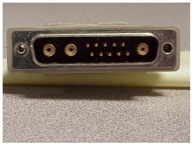
While the BNC connector provides very good video signal performance, its size and cost make it less than ideal for most volume applications. As workstation designs faced increasing cost and, more significantly, panel-space constraints, the need arose for a smaller, lower-cost interface system. Some manufacturers, notably Hewlett-Packard, opted to use the same 15-pin high-density D-subminiature connector as was becoming common in the PC industry (although with a slightly modified pinout; for example, many of HP’s designs using this connector provided a “stereo sync” signal in addition to the standard H and V syncs, and were capable of providing either separate TTL syncs or sync-on-green video). Most, however, chose to use a connector which became an “almost” standard in the workstation industry: the “13W3”, which combined pins similar to those used in the 15HD with three miniature coaxial connections, again in a “D”-type shell (Figure 9-9).
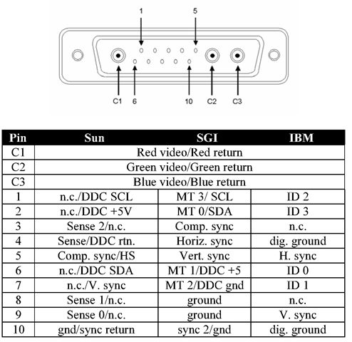
While many workstation manufacturers – including Sun Microsystems, Silicon Graphics (later SGI), IBM, and Intergraph – used the same physical connector, pinouts for the 13W3 varied considerably between them (and hence the “almost” qualifier in the above). In some cases (notably IBM’s use of this connector), there were different pinouts used even within a single manufacturer’s product line. Many of these are described in Figure 9-10 (although this is not guaranteed to be a comprehensive list of all 13W3 pinouts ever used!).
While the closed, bundled nature of workstation systems permitted such variations without major problems for most customers, it has made for some complication in the market for cables and other accessories provided by third-party manufacturers.
Figure 9-9 The 13W3 connector. This type, common in the workstation market, also uses a “D”-shaped shell, but has three true coaxial connections for the RGB video signals, in addition to 10 general-purpose pins. Unfortunately, the pin assignments for this connector were never formally standardized. Used by permission of Don Chambers/Total Technologies.
Figure 9-10 13W3 pinouts. This table is by no means comprehensive, but should give some idea of the various pinouts used with this connector, which has been popular in the workstation market. Note that alternate pinouts are shown for the Sun and Silicon Graphics (SGI) implementations; these are the original (or at least the most popular pre-DDC pinout) and the connector as it is used by that company with the VESA DDC standard. (“MT”, “Monitor Type”; both these and the “Sense” pins in the Sun definition serve the same basic function as monitor ID pins in the IBM pinout here, and in the original IBM definition of the “VGA” connector.)
EVC – The VESA Enhanced Video Connector
By the early-to mid-1990s, the video performance requirements of the PC market were clearly running into limitations imposed by the VGA connector and typical cabling. In addition, there was an expectation that the display would become the logical point in the computer system at which to locate many other human-interface functions – such as audio inputs and outputs, keyboard connections, etc. These concerns led to the start of an effort, again within the Video Electronics Standards Association (VESA), to develop a new display interface standard intended to replace the ubiquitous 15-pin “VGA.” A work group was formed in 1994 to develop an Enhanced Video Connector, and the VESA EVC standard was released in late 1995.
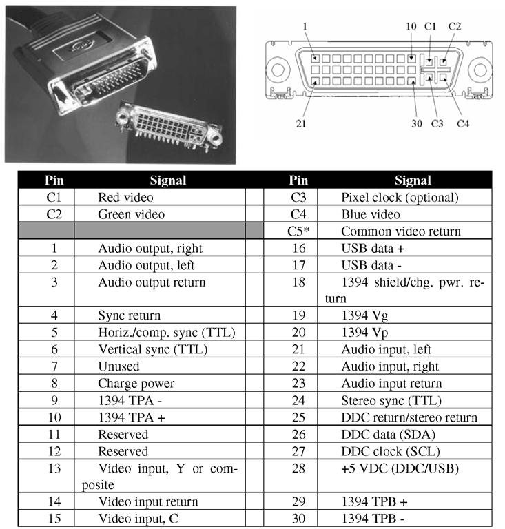
The EVC was based on a new connector design created by Molex, Inc. This featured a set of “pseudo-coaxial” contacts, basically four pins arranged in a square and separated by a crossed-ground-plane structure (in the mated connector pair) for impedance control and crosstalk reduction. The performance of this structure, dubbed a “Microcross™” by Molex, approximates that of the miniature coaxial connections of the 13W3 connector, while permitting much simpler termination of the coaxial lines and a smaller, lower-cost solution. In addition to the four “Microcross” contacts, which were defined as carrying the red, green, and blue video signals and an optional pixel clock, the EVC provided 30 general-purpose connections in three rows of ten pins each. These supported the usual sync and display ID functions, but also added audio input and output capability, pins for an “S-Video” like Y/C video input, and two general-purpose digital interfaces: the Universal Serial Bus (USB) and the IEEE-1394 high-speed serial channel, also known as “Firewire™”.The EVC pinout is shown in Figure 9-11.
Figure 9-11 The VESA Enhanced Video Connector and pinout. Note: “C5” is the crossed ground plane connection in the C1-C4 “MicroCross™” area.
While the EVC design did provide significantly greater signal performance than the VGA connector, the somewhat higher cost of this connector, and especially the difficulty of making the transition away from the de facto standard VGA (which by this time boasted an enormous installed base), resulted in this new standard being largely ignored by the industry. Despite numerous favorable reviews, EVC was used in very few production designs, notably late-1990s workstation products from Hewlett-Packard. But while the EVC standard may from one perspective be considered a commercial failure, it did set the stage for two later standards, including one which now appears poised to finally displace the aging VGA.
The Transition to Digital Interfaces
Soon after the release of the EVC standard, several companies began to discuss requirements for yet another display interface, to address what was seen as the growing need to support displays via a digital connection. During the mid- to late-1990s, several non-CRT-based monitors, and especially LCD-based desktop displays, began to be commercially viable, and many suppliers were looking forward to the time where such products would represent a sizable fraction of the overall PC monitor market. While such displays do not necessarily require a digital interface (and in fact, as of this writing most of the products of this type currently on the market provide a standard “VGA” analog interface), there are certain advantages to the digital connection that are expected to ultimately lead to an all-digital standard.
The result of these discussions was a new standards effort by VESA, and ultimately the release of a new standard in 1997. This was named the “Plug & Display” interface (a play on the “plug & play” catchphrase of the PC industry), and was not so much a replacement for the EVC as an extension of it. In fact, EVC was soon renamed to become an “official” part of the Plug & Display (or “P&D”) standard, as the “P&D-A” (for “analog only”) connector. The P&D specification actually defined three semi-compatible connectors; including the EVC or “P&D-A”, this system provided the option of an analog-only output, a combined analog/digital connection (“P&D-A/D”), or a digital-only output (“P&D-D”).
This was intentionally made slightly different from the original EVC design; this, plus the absence of the “Microcross™” section in the digital-only version, ensures that analog-input and digital-input monitors (distinguished by the plug used) would only connect to host outputs that would support that type.
The basis of the change from EVC to P&D was the idea that future digital systems would not require the dedicated analog connections for audio I/O and video input of the EVC.
Support for these functions would be expected to be via the general-purpose digital channels (USB and/or IEEE-1394) already present on the connector. This freed a number of pins in the 30-pin field of that connector for use in supporting a dedicated digital display interface, which permitting the analog video outputs of EVC to be retained. The digital interface chosen for this was the “PanelLink™” high-speed serial channel, originally developed by Silicon Image, Inc. as an LCD panel interface, and which was seen to be the only design providing both the necessary capacity and the characteristics required for an extended-length desktop display connection. This was renamed the “TMDS™” interface, for “Transition Minimized Differential Signalling,” in order to distinguish its generic use in the VESA standard from the Silicon Image implementations. The details of TMDS and other similar interface types are covered in the following topic.
Figure 9-12 A comparison of pinouts across the entire P&D family, including the P&D-A (formerly EVC). Used by permission of VESA.
The various pinouts of the full P&D system, including the EVC for comparison, are shown in Figure 9-12. Note that the analog-only and analog/digital versions remain compatible, at least to the degree that the display itself would operate normally when connected to either. (Again, a digital-input display would not connect to the analog-only EVC.) All P&D-compatible displays and host systems were required to implement the VESA EDID/DDC display identification system ,such that the system could determine the interface to be used and the capabilities of the display and configure itself appropriately. The P&D standard also introduced the concept of “hot plug detection,” via a dedicated pin. This permits the host system to determine when and if a display has been connected or disconnected after system boot-up, such that the display identification information can be re-read and the system reconfigured as needed to support a new display. (Previously, display IDs were read only at system power-up, and the system would then assume that the same display remained in use until the next reboot.)
While the P&D standard greatly extended the capabilities of the original EVC definition, it saw only slightly greater acceptance in the market. Several products, notably PCs and displays from IBM, were introduced using the P&D connector system, but again the need for these new features was not yet sufficient to outweigh the increased cost over the VGA connector, and again the inertia represented by the huge installed base of that standard. There was also a concern raised at this time regarding the various optional interfaces supported by the system. While the P&D definition provided for use of the Universal Serial Bus and IEEE-1394 interfaces, these were not required to be used by any P&D-compatible host, and several manufacturers expressed the concern that this would lead to compatibility issues between different supplier’s products. (This concern was a major driving force behind a later digital-only interface, the Digital Flat Panel or “DFP” connector, and ultimately the latest combined analog/digital definition, the Digital Visual Interface or “DVI”. Both of these are covered in the following topic.)
The Future of Analog Display Interfaces
At present, the end may seem to be in sight for all forms of analog display interfaces. Both television and the computer industry have developed all-digital systems which initially gained some acceptance in their respective markets, and which do have some significant advantages over the analog standards which they will, admittedly, ultimately replace. However, this replacement may not happen as rapidly as some have predicted. For now, the CRT remains the dominant display technology in both markets, and digital interfaces really provide no significant advantage for this type if all they do is to duplicate the functioning of the previous analog standards. And, as has been the case with many of the interface standards discussed in this topic, the fact that analog video in general represents a huge installed product base makes a transition away from such systems difficult. A change to digital standards for all forms of display interfaces is not likely to be achieved until such systems provide a clear and significant advantage, in cost, performance, or supported features, over the analog connections. Digital interface standards have yet to realize this necessary level of distinction over their analog predecessors, but as will be seen in the following topic, they are rapidly developing in this direction.
