The “F” connector
A step up from the “RCA” type for high-frequency connections, if only due to being a better match to the RG-59 type coaxial cable common in consumer video interconnects, is the “F” connector type. This again provides a single “signal” contact, which in this case is generally the center conductor of the coaxial cable itself. The “shield” connection is provided via the outer cylindrical shell or barrel. The outer shell of the jack in this type is threaded, but the plug may provide either a friction-fit stationary outer shell or a threaded barrel. The connector is available in 75-Ω designs, and is typically a very inexpensive and simple connector to use; a crimp connection to the coaxial cable’s shield is common. Due primarily to the use of the center conductor of the cable itself as the center pin, though, this type is not especially rugged and should be avoided in applications where frequent insertions and removals are expected. The “F” connector is quite common as an antenna input for television receivers, and as a composite video input or output connector for all consumer video equipment.
The BNC connector
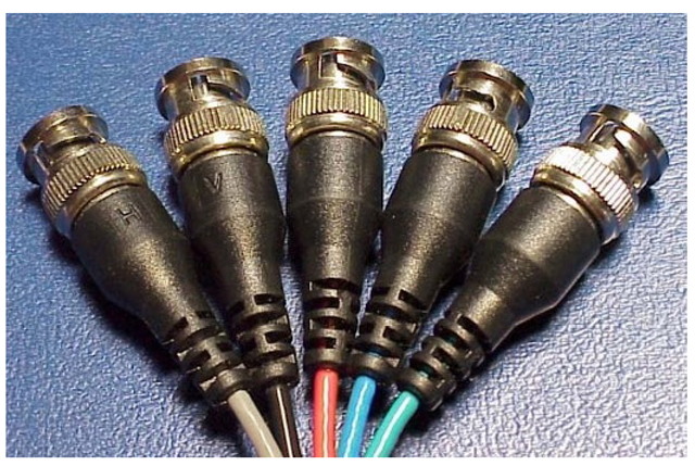
The BNC (“Bayonet Neill-Concelmann”, named for its designers) connector is a very rugged, compact, and relatively high-performance connector which provides a good match to coaxial cables up to the standard RG-59 size (special BNCs may also be found to accommodate larger cables). Shown in Figure 8-12, the plug provides a separate center pin, typically soldered or crimped to the coax center conductor, and an outer barrel for the “shield” contact. The rotating barrel provides a positive lock to the jack, by engaging two small pins protruding from the outer cylindrical portion of the jack (a “bayonet” connection, hence the name). While not as inexpensive as the “F” type, BNCs provide a much more positive connection, and are usable to very high frequencies. This type, due to its higher cost, is generally found only on high-end consumer equipment, but is common in professional video gear and has also been widely used in the computer industry. It is important to note, however, that the connector itself and standard cable assemblies using it are available in both 50-0hm and 75-ohm versions. Care must be taken to ensure that only 75-Ω types are used in standard video applications.
Figure 8-12 BNC connectors.
The N connector
Similar in appearance to the BNC, the somewhat-larger “N” connector differs in two significant points. First, the outer barrel of the plug, and the mating surface of the jack, employ a threaded connection rather than the bayonet type. The connector also is distinguished by a separate cylindrical contact between the center pin and the outer barrel, and so does not rely solely on the barrel to provide the “shield” or “return” connection. The “N” connector is a very high-performance, precision type, but relatively costly and more difficult to attach to the cable. Use of this type is restricted to professional-level studio and test equipment.
The SMA and SMC connector families
These connectors, generally found only in professional equipment and precision test and measurement gear, are precision coaxial connectors intended for use with miniature coax.
The “S-Video”/mini-DIN connector
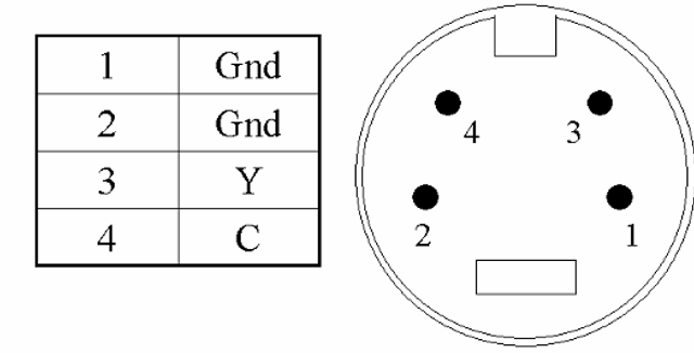
A very popular connector in consumer video equipment, including television receivers, video-cassette recorders (VCRs), camcorders, etc., is the “S-Video” connector, based on the standard 4-pin miniature DIN connector (Figure 8-13). This provides separate luminance (Y) and chrominance (C) connections, and has become so associated with the Y/C interface that any such connection (even if physically separate connectors are used for the Y and C signals) is often referred to as “S-Video.” The connector is relatively inexpensive and works reasonably well in this application, but does not provide a true coaxial, impedance-matched connection and so would not be suitable for similar use at higher frequencies. Alternate types, also confusingly referred to as “S-Video” connectors, use the 7-pin miniature DIN (the same size and overall shape as the 4-pin version), but carry either an I2C interface (for control functions), or a separate composite video signal.
Figure 8-13 “S-Video” 4-pin mini-DIN connector (output jack) and pinout.
The SCART or “Peritel” connector
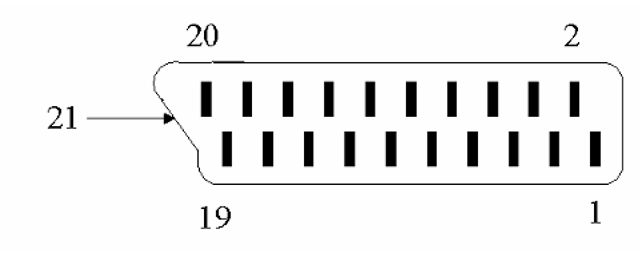
Possibly best viewed as the European counterpart to the S-Video connection, the SCART (Syndicat des Constructeurs d’Appareils Radiorécepteurs et Téléviseurs) connector (Figure 8-14), also known as the “Peritel” connector, also supports separate Y and C video connections. In addition, this connector provides stereo audio inputs and outputs and a separate composite video connection. An alternate pinout has also been defined for use in RGB systems. Status pins (both input and output) are used to define the active video signals at any given time, permitting devices to switch connections automatically.
Figure 8-14 The SCART or “Peritel” connector. There are at least two pinouts in use for this connector, one intended for RGB video and the other intended for “S-Video” compatibility. These are as listed in Table 8-4.
Table 8-4 SCART/Peritel connector pinouts.
|
Pin no. |
Type 1 assignment (“RGB”) |
Type 2 assignment (“S-Video”) |
|
1 |
Audio out B/right |
Audio out B/right |
|
2 |
Audio input B/right |
Audio input B/right |
|
3 |
Audio out A/left (or mono out) |
Audio out A/left (or mono out) |
|
4 |
Audio return |
Audio return |
|
5 |
Blue video return |
Ground |
|
6 |
Audio input A/left (or mono in) |
Audio input A/left (or mono in) |
|
7 |
Blue video input |
- |
|
8 |
Function selecta |
Function select1 |
|
9 |
Green video return |
Ground |
|
10 |
Data 2 |
Data 2 |
|
11 |
Green video input |
- |
|
12 |
Data1 |
Data 1 |
|
13 |
Red video return |
Chrominance return |
|
14 |
Ground |
Ground |
|
15 |
Red video input |
Chrominance (C) input |
|
16 |
RGB/composite switchingb |
- |
|
17 |
Ground |
Luminance return |
|
18 |
Ground |
- |
|
19 |
Video out (composite) |
Video out (composite) |
|
20 |
Video in (composite) |
Luminance (F) input |
|
21(shell) |
Common ground (shield) |
Common ground (shield) |
a The function select input switches the equipment between “standard TV” (0-2V), “widescreen” (58V), and “AV” (9.5-12V) modes. If the video source sets this pin to either of the latter two states, the SCART input is automatically used; the two differ only in that video processing to handle “anamor-phic” 16:9 programming is enabled in the “widescreen” mode.
b The RGB/composite switch input determines the video inputs in use; when high (1-3V), the RGB video inputs are used, and when low (0-0.4V) the composite input is used.


