Supplemental General-Purpose Interfaces
As noted previously, the recent trend has been for more general-purpose interfaces to be included in the display interface definition, along with the primary video channel. This permits a wide variety of additional data and control functions to be communicated to the display. In addition to providing identification and control of the display itself, as covered in the previous sections, the addition of such channels to the display interface permits the display to host numerous other devices and peripherals. In many applications, for instance, the display is a logical point at which to centralize those functions through which the user interacts with the system. It is the one major system component which can be counted on to be located in the immediate vicinity of the user, and also can be used to provide power to additional devices at only a slight incremental cost in the display power supply. Therefore, many display designs also incorporate input devices (such as touchscreens, trackballs, keyboards, etc.), removable-media mass storage, audio input and/or output, or at least the connectors necessary for the attachment of these.
Until recently, the primary distinguishing features of such additional interfaces, as compared with the video channel itself, were that they were relatively low-capacity, bidirectional, and digital connections. As the display interface proper changes from the analog standards of the past to the new digital types, these distinctions become less important and the need for such physically separate general-purpose interfaces less clear. The sole additional requirement for supporting these functions which has not yet generally been provided by the display interface is a “back channel,” some means for communicating data from the display to the host system. This is also likely to change, given the needs of more “network-like” systems such as the Digital Packet Video Link discussed in the previous topic. As display systems move to this model, it is likely that all communications between the host and display – including all command, ID, and supplemental functions, as well as the video data itself – will be carried over a single common channel, supported by a somewhat lower-capacity back channel.
Until such a system is widely adopted, several general-purpose digital interfaces will see continued support on standard display connector definitions. The I2C interface, in the form of the VESA Display Data Channel standard, has already been discussed, as has the now-obsolete ACCESS.bus specification which was based upon it. At this point, there are two such systems in widespread use: the Universal Serial Bus, or USB, and the IEEE-1394 standard, also known by the trade names “Firewire ” and “i-Link ”, which refer specifically to the implementations of this standard by Apple Computer and Sony Corp., respectively. No other challengers have appeared, and it seems likely that these will continue to be the dominant standards for such applications. While these have been mentioned earlier in relation to the recent display interface standards that support them, they will now be covered in greater detail here.
The Universal Serial Bus
The Universal Serial Bus, or “USB” as it is commonly known, was originally defined as a low-to-medium speed interface intended primarily for the connection of human input devices (such as keyboards, mice, etc.) and digital audio peripherals. Using a simple, four-wire physical connection, comprising a single bidirectional data pair, a +5 VDC power line, and a ground, the USB 1.0 specification permitted two modes of operation to meet the needs of these peripherals. In the “low-speed” mode, a peak raw data rate of 1.5 Mbits/s is supported; in the faster, standard mode, USB provides a peak rate of 12 MBits/s. (In realistic situations, accounting for the overhead of the system and management of multiple devices on a given physical interface, more typical observed data rates are in the range of 700-800 kbytes/s.) This is sufficient to support simultaneous operation of multiple low-speed devices such as keyboards, etc., along with perhaps one or two peripherals requiring higher data rates, such as digital audio (speakers) or a low-to-medium resolution video camera.
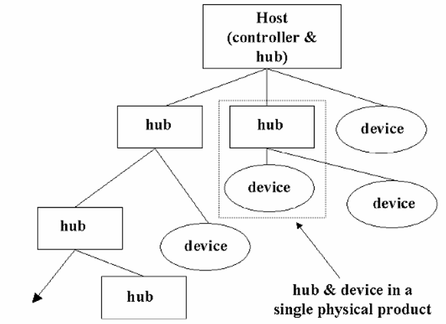
Despite its name, USB is not truly a “bus” system. Rather, it employs a “tiered-star” topology, in which a single controller manages all peripheral devices as the “root” of a treelike arrangement (Figure 11-2). From the root controller, devices are connected via “hubs” which provide for branching at each level. The specification permits tiering up to five levels deep, although there is no set limit on the number of separate “branches” (“downstream” ports) which may be supported by each hub. Hubs may be either “powered” or “unpowered”; as the name would imply, a powered hub has its own power supply, and does not rely on the +5 VDC line provided by its “upstream” connection. In either case, all USB “downstream” ports (such as those provided by the host or a hub for the connection of peripherals) must provide up to 500 mW of power (100 mA) on the +5 VDC line when a peripheral is connected and initialized. Under host control, a given peripheral may then be provided with up to 2.5 W (500 mA), if this remains within the limitations of the host or hub.
Figure 11-2 USB “tiered-star” topology. A single controller may support up to 127 devices, but the system is limited to five levels of tiering. This is only the logical topology; physical products may combine hubs and logical USB devices as desired.
USB was designed to permit “hot plugging” of all peripheral devices, meaning that any device may be connected to or disconnected while the rest of the system remains powered up. Upon connection of each device (or at initialization of a previously connected set of devices at system power-up), the device is identified by the host controller and assigned an address within the current structure. The speed at which the device operates is also identified, and the port to which it is connected is then configured to provide the desired level of service (either the low-speed 1.5 Mbit/s mode or the full 12 Mbit/s). As each device is identified, the proper driver for that device or device class may be loaded by the host system. The USB specifications provide for sufficient standardization of device operation that a “generic” USB driver, at least for a given device class (such as human-input devices), may typically be used with all devices of that class connected to the system.
USB provides for a mix of isochronous and non-isochronous (or “asynchronous”) data streams to be supported simultaneously; as noted in the previous topic, an “isochronous” data transmission is one in which the receipt of the data by the receiving device is time-critical. An example of this is the transmission of digital audio, in which the data representing each sample must be received within the defined sample period. To support such transmissions, the USB controller allocates the available capacity on the interface as best it can, giving priority to devices requiring such isochronous flow. Thus, it is possible for one or more isochronous devices to “hog the bus” at the expense of others.
For any transmission type or rate, the USB interface transmits data serial on a single differential pair, in a “half-duplex” mode. All operations must be initiated by the host controller; no direct communications (i.e., “peer-to-peer” transmissions) are permitted between peripherals. Owing to the transmission protocol and format, the maximum length of any USB cable is strictly limited to a maximum of 5 m (slightly under 16.5 feet); to extend any branch beyond this limit requires at least one intermediate hub. A given physical product may contain both device and hub functions, although these will still be treated as logically separate blocks by the controller. As a device is a separate function from a hub, such configurations can appear to provide “daisy-chain” connections, although the limitation to five levels in the tiered-star topology represents a hard limit on the length of such a “chain.” For maximum flexibility, then, most hubs will provide multiple downstream ports.
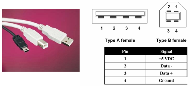
The specification defines two physical connectors, shown in Figure 11-3. The “type A” connector, the more rectangular, “flatter” of the two, is used as the “downstream” connection from hosts and hubs. The “type B” connector, which is more nearly square in cross-section, is used on USB peripherals.
In April, 2000, a new USB consortium led by Compaq, Hewlett-Packard, Lucent, NEC, Intel, and Microsoft released the USB 2.0 specifications, which greatly increased the data rate supported by the system. USB 2.0 remains completely compatible with the earlier specification (which in its latest revision was “USB 1.1”), but permits data rates up to 480 Mbits/s. USB 1.1 peripherals can be used in a USB 2.0 system, although the port to which they are connected will then be configured by the host controller to either the 12 Mbit/s or I.5 Mbit/s modes, prohibiting higher-speed devices to be connected downstream of that port. USB 2.0 and USB 1.1 hubs may be mixed in a given system, but the user must be aware of which is which such that the higher-speed USB 2.0 devices are not connected to a hub which cannot support them. Existing USB cabling, if compliant with the original standard, is completely capable of supporting the faster rate.
Figure 11-3 USB connectors and pinouts. As shown in the photograph, USB connectors come in several styles and sizes; this picture shows the “A” and “B” type standard-sized connectors (in white), plus an example of a mini-USB connector. The “A” connector, the flatter of the two, is typically the “upstream” connection – the output of a hub or controller, for example. The more squared-off “B” type connector is the “downstream” connection, used at the input to USB devices.
IEEE-1394/”FireWire™”
In 1986, Apple Computer developed a new high-speed serial interface which was introduced under the name “FireWire™.” The specifications for this interface were later standardized by the Institute of Electrical and Electronic Engineers as IEEE-1394, released in its original form in 1995. Currently, this interface is commonly known under both the “1394” and “FireWire™” names, although properly the latter refers only to Apple’s implementation (and is a trademark of that company). Other proprietary names for this interface have also been used by various companies, such as “i.Link™” for Sony’s implementation. We refer to it here simply as “1394.” This standard has become the digital interface of choice in several markets, especially in both consumer and professional digital audio/video (A/V) systems. IEEE-1394 has also been selected as the underlying physical/electrical interface standard for the VESA/CEA Home Network standard.
In many respects, 1394 resembles USB; both are serial interfaces intended for the easy connection of various types of devices in a “networked” manner. Both permit “hot-plugging” (connection and disconnection of devices at any time), and both provide for power to be carried by the physical interface along with data. And, with the recent introduction of the USB 2.0 specification, the data rates supported are at least comparable. The original IEEE-13941995 standard defined operation at 100, 200, and 400 Mbits/s.
However, there are significant differences between the two that continue to distinguish them in the market. The most obvious is in the topology of the system. Unlike USB, which relies on a single controller as the master of the entire “tree” of hubs and devices, 1394 is based on peer-to-peer communications. Any device connected to the interface may request control of the bus, under defined protocols and capacity-allocation limits; there is no single master controller. 1394 has a cable length limit similar to USB’s – in this case, 4.5 m under the original specification – but permits the use of “repeaters” to extend the connection up to 16 times between devices. Note that longer cable lengths may be possible at lower data rates, or using expected future specifications for improved cabling. 1394 also lends itself to optical connections, which may permit repeaterless connections of 50 to 100 m or more. Each 1394 bus can support up to 63 separate devices, but there is also a provision for “bridges” between buses. A maximum of 1,023 buses may be interconnected via 1394 bridges, for an ultimate limit of 64,449 interconnected devices.
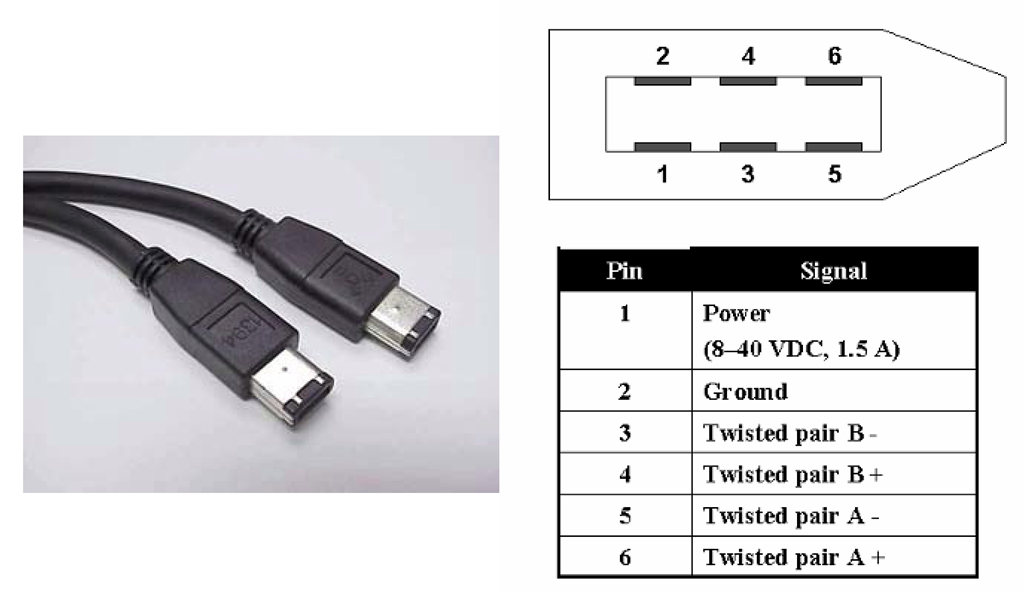
Physically, the standard 1394 connector provides six contacts in a rectangular shell which has a slight resemblance to the USB Type A connector. This same connector type, however, is used for all 1394 ports. The connector and its pinout are shown in Figure 11-4. A 1394 cable comprises two twisted pairs, individually shielded, for the data channels; these are crossed between the data contacts at each end, such that each device sees a separate “transmit” and “receive” pair. The remaining two contacts are for power and ground, in this case a DC supply of up to 1.5 A at 8 to 40 VDC. An overall shield is also specified, covering all six conductors. A smaller 4-pin connector has also been used in some products, which deletes the power connection and its return.
Figure 11-4 IEEE-1394/”FireWire™” connector and pinout. Unlike USB, the IEEE-1394 standard uses the same connector at both ends of the cable. The interface is based on two twisted-pair connections, both carrying data and data strobe signals, but these are switched from one end of the cable assembly to the other such that each device sees a “transmit” and “receive” pair. The pinout shown here is for the male connector.
Like USB, the 1394 standard defines support for both isochronous and asynchronous communications, and so also lends itself well to supporting timing-critical, streaming-data applications such as digital video or audio transmission. Any single device may request up to 65% of the available capacity of the bus, and a maximum of 85% of the total capacity may be allocated to such requests across all devices on the bus. This ensures that some capacity will always be available for asynchronous communications, preventing such from being completely shut down through an “overload” of isochronous allocations.
Also like USB, the 1394 standard continues to be developed. A recently completed revision to the original specifications will extend the capacity of this system beyond the original 100/200/400 Mbit/s levels, adding 800, 1600, and 3200 Mbit/s as supported rates. With this increase in capacity, 1394 can continue to support the high-speed connections required by mass storage devices, high-definition television, and multiple digital audio streams.
The slightly more complex cabling design, and especially the more elaborate protocol and the requirement that all devices be peers (and so effectively have “controller” capability) result in the 1394 bus being somewhat more costly to implement, overall, than the USB system. However, this increased cost does buy increased capabilities, as described above. Both systems are likely to continue to co-exist, with USB being the more attractive choice as a “desktop” PC peripheral interconnect, and 1394 remaining the standard for digital A/V system connections and “home network” and similar applications.


