Traditional wireless LAN (WLAN) deployments used X number of access points (AP) spread across the premises that needed wireless coverage. With standalone, each AP was an individual entity that needed configuration, monitoring, provisioning, and so on. If these tasks were required for only a few devices, they would be manageable; however, when you are talking about a full enterprise WLAN that might be offering advanced services such as Voice over Wireless, the management of each AP becomes daunting.
You can add additional complexities to an enterprise WLAN, such as radio frequency (RF) management (dynamically adapt to changes in the environment) and security, which is critical in wireless because of the broadcast nature of the medium.
Unless some kind of coordination is put in place, enterprise WLANs will hit scalability and practical limitations sooner or later. The Lightweight Access Point Protocol (LWAPP) was designed to overcome those limitations and expand the feature set and uses of WLANs without increasing the management burden or weakening the security standpoint of the enterprise.
LWAPP is not a "general" solution. In some scenarios, a traditional AP is best—for example with Point to Point bridging, where no coordination or RF monitoring is needed because of the characteristics of the controlled environment for this deployment.
Given the explosion in growth for wireless networks and the ubiquity that these services have in the current enterprise, vendors have implemented multiple approaches to simplify the operation and deployment of wireless services.
Proposed as a potential way of simplifying the operation of wireless networks, LWAPP has been implemented across the Cisco Unified Wireless Networks set of products (Wireless LAN Controller [WLC], APs, and related devices) from their initial software release until version 5.1. New versions, in particular 5.2, are using Control and Provisioning of Wireless Access Points (CAPWAP) as the base protocol.
Formally speaking, LWAPP is described in several drafts of the Internet Engineering Task Force (IETF) CAPWAP working group, the latest of which (at press time) is Version 4 (draft-ohara-capwap-lwapp-04.txt). Cisco Systems, Inc. submitted this draft for standardization in 2004, and through a protocol evolution, CAPWAP is the end result.
The ideas behind LWAPP are as follows:
■ Move the traffic forwarding, certain security functions such as authentication, and policy functions from the edge (AP) toward a centralized point.
■ Simplify the AP, because higher-level functions are now done separately, which reduces AP complexity and cost.
■ Provide an encapsulation and transport mechanism for wireless traffic.
■ Centralize AP configuration and management.
LWAPP is a way for an AP to communicate directly with a management entity—the WLC. This new approach to the wireless networks was designed to have nodes or points of presence throughout a network. These node devices would not require configuration and would rely on a master device for their configurations and instructions. These nodes would exist to provide a point in the network to which a wireless user can connect. After a user connects, all traffic going to this node would be sent to the master device. The master device would then determine where in the network or on what virtual LAN (VLAN) the packet needed to go. This approach offers many advantages over the single device configuration setup but requires a protocol to provide constant connectivity and direction for these devices to operate. LWAPP provides the solution.
Although in official standard documents the APs are referred to as wireless termination points (WTP) and the WLCs as access controllers (AC), this topic uses the more commonly known terms AP and WLC, or controller, to refer to the "wireless" and "aggregation" points respectively, to make it easier to follow the discussions throughout the topic.
Quick Protocol Overview
Briefly, LWAPP operation is as follows:
Step 1. AP tries to discover a list of valid WLCs with which to associate or join.
Step 2. When this discovery process is successful, the AP selects a WLC and then tries to join it.
Step 3. Upon join, the AP checks to see if the software version it is running matches that of the WLC. If it does not, the AP initiates an upgrade process (image).
Step 4. If an image process was done, the AP reloads and goes through the discovery/join process again. If the AP now has the correct software version, it receives the configuration from the WLC.
Step 5. Depending on the configuration received, the AP might need to do a reload (for example, the AP mode is changed) and pass through the discovery/join steps again.
Step 6. After newly joining and confirming that it now has the correct configuration and image, the AP transitions into run status and starts servicing clients.
Step 7. During this run status, the AP periodically sends RF and security monitoring information to the WLC for aggregation and processing.
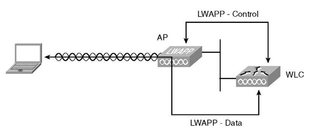
LWAPP has two main traffic types, as seen in Figure 3-1:
■ Control: Management traffic between AP and WLC. It is a control channel for configuration, session management, firmware management, and so on. Traffic is encrypted and authenticated.
■ Data: Wireless traffic, encapsulated, sent between AP and WLC. You can make an analogy to a GRE-Tunnel.
Figure 3-1 LWAPP Traffic Types
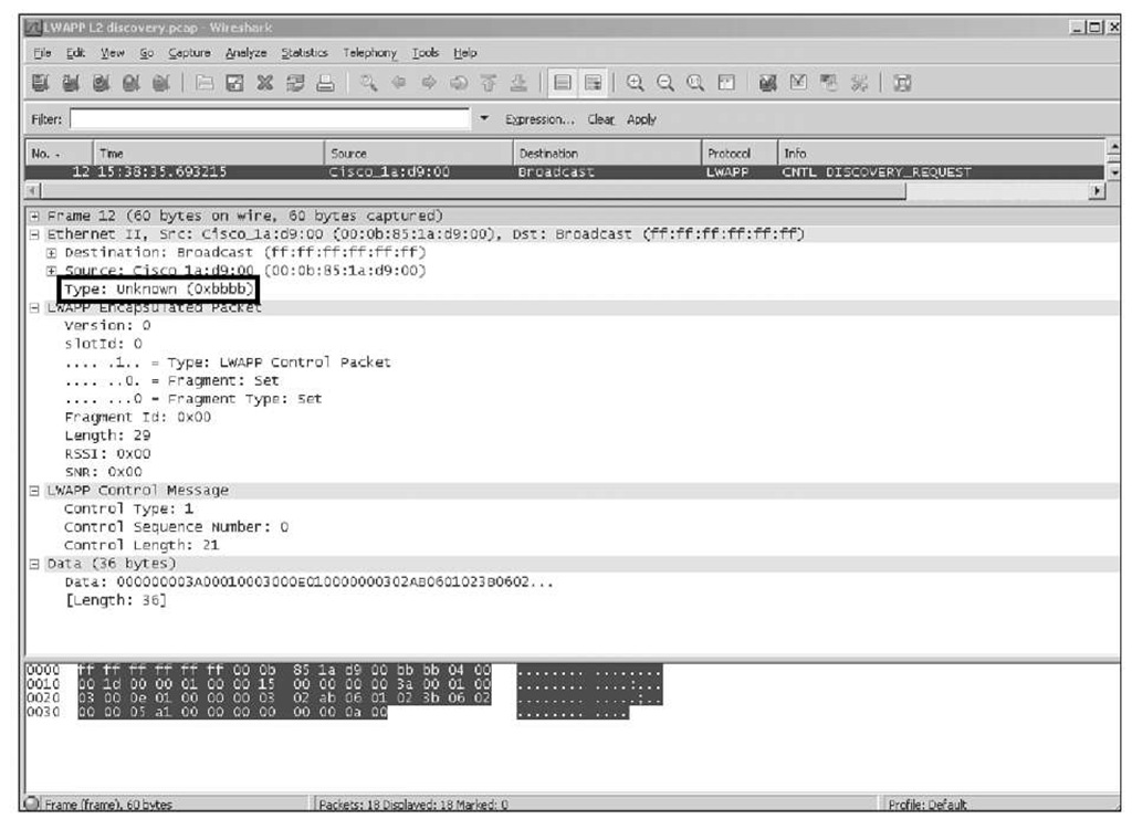
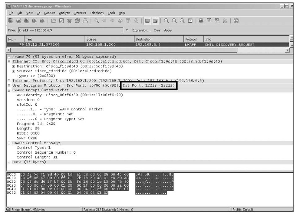
As Figure 3-2 and Figure 3-3 illustrate, LWAPP has two encapsulation types:
■ Layer 2: All communication between the AP and WLC is done on top of native 802.3 Ethernet frames, with an Ethertype of 0xbbbb or 0x88bb, depending on the release.
■ Layer 3: LWAPP is carried over IP/User Datagram Protocol (UDP), using port numbers 12222 and 12223 (data and control, respectively).
Figure 3-2 LWAPP Layer 2 Encapsulation
Figure 3-3 LWAPP Layer 3 Encapsulation
Layer 2 is mostly for legacy deployments; it is not supported on newer APs. It is deprecated in code Releases 5.2 and higher, and it suffers from scalability issues. Layer 3 is the recommended mode of operation, where the WLC and APs have IP addresses.
Although LWAPP State Machine has several states, the most important ones are as follows:
■ Discovery: The AP is trying to learn a list of valid WLCs to join.
■ Join: The AP has determined the preferred WLC and is trying to join it.
■ Image: The AP has detected that it is not running the same version of software as the WLC, so it is updating its firmware.
■ Configure: The AP has joined a WLC and is now receiving new operating parameters/configuration.
■ Run: The AP has joined, is configured, and is using the same software version as the WLC. This is the normal state of operation.
LWAPP divides the work between the AP and the WLC and assigns different functions to each component (Split MAC Architecture):
■ AP: In charge of beacons, probe response, power management and buffering, scheduling, queuing, 802.11 auth response, and encryption.
■ WLC: In charge of association processing, traffic forwarding to the network, reasso-ciation processing, classifying, 802.1x/EAP, and key handling.
Note Split MAC Architecture was the name initially used for LWAPP, using the acronym of SPAM, which you can still find in WLC debug messages such as the following:
Thu Aug 27 08:07:34 2009: 00:1d:a1:cd:dd:6c Length: 8/8 bytes (spamControlMsg_t)
Thu Aug 27 08:07:34 2009: Send AP Timesync of 1251360454 source MANUAL Thu Aug 27 08:07:34 2009: 00:1d:a1:cd:dd:6c Length: 8/16 bytes (spamEncodeTimesyncPayload)
For obvious reasons, the protocol was later renamed LWAPP, but in the code, you will still see SPAM as the name for the component handling LWAPP. This is not so easy to change.


