A distribution system port connects the controller to a neighbor switch and serves as the data path between these two devices. This topic discusses a few common methods on the models that have these options.
Cisco 4402 controllers have two Gigabit Ethernet distribution system ports, each of which is capable of managing up to 48 access points (AP). The Cisco 4404 controllers have four Gigabit Ethernet distribution system ports, each of which is capable of managing up to 48 APs per port. The 4404-25, 4404-50, and 4404-100 models allow a total of 25, 50, or 100 APs to join the controller. The Gigabit Ethernet ports on the 4402 and 4404 controllers accept these SX/LC/T small form-factor plug-in (SFP) modules:
■ 1000BASE-SX SFP modules, which provide a 1000-Mbps wired connection to a network through an 850nM (SX) fiber-optic link using an LC physical connector
■ 1000BASE-LX SFP modules, which provide a 1000-Mbps wired connection to a network through a 1300nM (LX/LH) fiber-optic link using an LC physical connector
■ 1000BASE-T SFP modules, which provide a 1000-Mbps wired connection to a network through a copper link using an RJ-45 physical connector
The Cisco 5508 controllers have eight Gigabit Ethernet distribution system ports through which the controller can manage multiple APs. The 5508-12, 5508-25, 5508-50, 5508-100, and 5508-250 models allow for 12, 25, 50, 100, or 250 APs to join the controller. Cisco 5508 controllers have no restrictions on the number of APs per port. However, Cisco recommends using link aggregation (LAG) or configuring dynamic AP-Manager interfaces on each Gigabit Ethernet port to automatically balance the load. If more than 100 APs are connected to the 5500 series controller, make sure that more than one Gigabit Ethernet interface is connected to the upstream switch. The Gigabit Ethernet ports on the 5508 controllers accept these SX/LC/T small form-factor plug-in (SFP) modules:
■ 1000BASE-SX SFP modules, which provide a 1000-Mbps wired connection to a network through an 850nM (SX) fiber-optic link using an LC physical connector
■ 1000BASE-LX SFP modules, which provide a 1000-Mbps wired connection to a network through a 1300nM (LX/LH) fiber-optic link using an LC physical connector
■ 1000BASE-T SFP modules, which provide a 1000-Mbps wired connection to a network through a copper link using an RJ-45 physical connector
The Cisco Catalyst 6500 Series Switch Wireless Integrated Services Module (WiSM) and the Cisco 7600 Series Router WiSM have eight internal Gigabit Ethernet distribution system ports (ports 1 through 8) that connect the switch or router and the integrated controller. These internal ports are located on the backplane of the switch or router and are not visible on the front panel. Through these ports, the controller can support up to 300 APs.
The controller network module within the Cisco 28/37/38xx Series WiSM can support up to 6, 8, 12, or 25 APs (and up to 256, 256, 350, or 350 clients, respectively), depending on the version of the network module. The network module supports these APs through a Fast Ethernet distribution system port (on the NM-AIR-WLC6-K9 6-access-point version) or a Gigabit Ethernet distribution system port (on the 8-, 12-, and 25-access-point versions and on the NME-AIR-WLC6-K9 6-access-point version) that connects the router and the integrated controller. This port is located on the router backplane and is not visible on the front panel. The Fast Ethernet port operates at speeds up to 100 Mbps, and the Gigabit Ethernet port operates at speeds up to 1 Gbps.
The Catalyst 3750G integrated Wireless LAN Controller (WLC) switch has two internal Gigabit Ethernet distribution system ports (ports 27 and 28) that connect the switch and the integrated controller. These internal ports are located on the switch backplane and are not visible on the front panel. Each port is capable of managing up to 48 APs. However, Cisco recommends no more than 25 APs per port due to bandwidth constraints. The -S25 and -S50 models allow a total of 25 or 50 APs to join the controller.
Each distribution system port is, by default, an 802.1Q VLAN trunk port. The VLAN trunking characteristics of the port are not configurable. Some controllers support LAG, which bundles all the distribution system ports of the controller into a single 802.3ad port channel. Cisco 4400 series controllers support LAG in software Releases 3.2 and later; Cisco 5500 series controllers support LAG in software Releases 6.0 and later; and LAG is enabled automatically on the controllers within the Cisco WiSM and the Catalyst 3750G integrated WLC switch.
Regardless of operating mode, all controllers use the network as an 802.11 distribution system. Regardless of the Ethernet port type or speed, each controller monitors and communicates with its related controllers across the network. Two common methods are typically used when connecting the WLCs that have multiple ports to the neighboring switch. One method is with multiple independent links managed on their own, and the other method is similar to a port channel setup or LAG. LAG came out after the original idea of creating an additional AP-Manager on a port to manage additional APs.
Multiple AP-Manager Support
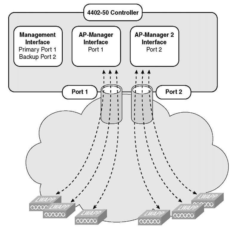
If you are not using LAG, how do you utilize the other ports to support additional APs? You have to create additional AP-Manager interfaces to manage the ports so they are able to handle WLC-to-AP communications. After you do this, APs can start using these ports to join the WLC. One of the key elements to remember is that this was only intended to be used with the Cisco 4400 series standalone controllers. You will not have this option for any of the integrated WLCs because they will only use a LAG setup. Refer to Figure 7-1 for a multiple AP-Manager setup. In this setup, both AP-Managers have been enabled for AP support. If this were a 4404 and two ports were configured as such and the other two ports were active then you would have support for additional APs, and two redundancy ports.
Figure 7-1 Multiple AP-Manager Setup: Two AP-Managers
For best housekeeping, configure the ports in sequential order such that AP-Manager interface 2 is on port 2, AP-Manager interface 3 is on port 3, and AP-Manager interface 4 is on port 4. Another common question that comes into play here is this: Do the
AP-Managers need to be in the same VLAN? The answer is no. The AP-Manager interfaces need not be on the same VLAN as the other AP-Managers or the Management interface. However, from a management and troubleshooting perspective, it is highly recommended that you configure all AP-Manager interfaces on the same VLAN or IP subnet.
Note You must assign an AP-Manager interface to each port on the controller.
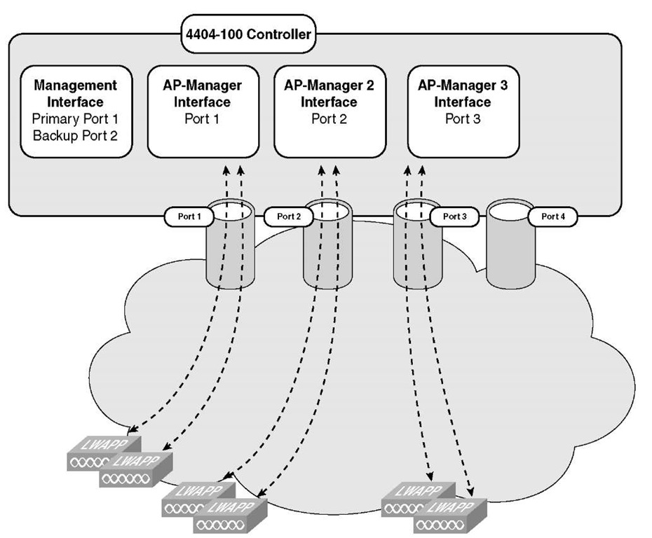
Another key question is this: How do the AP-Managers work, and where do they fit into the normal AP join process? Before an AP joins a controller, it sends out a discovery request. From the discovery response that it receives, the number of AP-Manager interfaces available and the capacity of each manager is relayed to the AP in the discovery response. Unless another form of load balancing exists, the AP joins the AP-Manager with the lowest capacity. The result is a round robin load-balancing effect. Another important fact to remember about AP-Managers is that for each AP-Manager port created, you lose a port for redundancy. Refer to Figure 7-2; when we refer to losing a port for redundancy. We are referring to port redundancy, not port redundancy, for AP support.
Figure 7-2 Multiple AP-Manager Setup: Three AP Managers
Note APs may not be distributed completely evenly across all the AP-Manager interfaces, but a certain level of load balancing occurs.
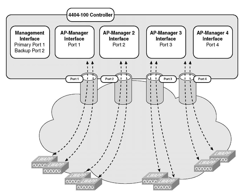
If you consider a scenario in which a WLC has all its ports assigned as AP-Managers, for a total of 100 APs (see Figure 7-3), how would this affect the AP failover and port failover? One key concept in this design is that it has the advantage of load-balancing all 100 APs evenly across all four AP-Manager interfaces. If one of the AP-Manager interfaces fails, all the APs connected to the controller would be evenly distributed among the three available AP-Manager interfaces. For example, if AP-Manager interface 2 fails, the remaining AP-Manager interfaces (1, 3, and 4) would each manage approximately 33 APs.
Figure 7-3 Multiple AP-Manager Setup: Four AP Managers
A key element to remember is that for every port that is physically connected and turned on, there must be an AP-Manager for each port. Having two AP-Managers for the 4402 or four for the 4404 is mandatory if all ports are to be used.


