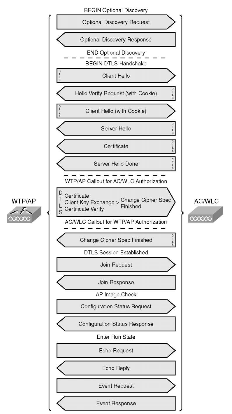
As mentioned earlier, the CAPWAP session is similar to LWAPP. The main difference is the use of DTLS for authentication (DTLS-handshake) and tunnel encryption (DTLS-application data). The following is an overview of the session establishment process:
Step 1. Discovery request (optional)
Step 2. Discovery response
Step 3. DTLS session establishment; all messages below will be encrypted (DTLS application data)
Step 4. Join request
Step 5. Join response
Step 6. Configuration status request
Step 7. Configuration status response
Step 8. Run state
Figure 4-4 outlines the detailed CAPWAP packet flow.
Figure 4-5 shows the complete CAPWAP protocol state machine. Use it as reference while reading CAPWAP debugs. You will find the actual states printed in the CAPWAP debugs on the controllers or APs.
You can find a detailed description of the various state transitions and the events that cause them in section 2.3.1 of RFC 5415 at http://www.ietf.org/rfc/rfc5415.txt.
For simplicity, Figure 4-5 uses the same transition index (ASCII character) as has been used in RFC 5415.
Certain debugs such as debug capwap event enable are printing the CAPWAP state in cleartext:
Figure 4-4 CAPWAP Packet Flow
Figure 4-5 CAPWAP Protocol State Machine
Other CAPWAP debugs such as debug capwap detail enable are printing the internal used state-ID only:
Use Table 4-2 to find the corresponding CAPWAP state.
If you compare those states with those in LWAPP,you will see that the only difference between CAPWAP and LWAPP is the fact that CAPWAP uses DTLS encryption, which also includes a handshake negotiation.
Table 4-2 CAPWAP State ID in Controller Debugs_
|
ID |
CAPWAP State |
|
0 |
NO STATE |
|
1 |
INIT |
|
2 |
DISCOVERY |
|
3 |
DTLS SETUP |
|
4 |
DTLS TEARDOWN |
|
5 |
JOIN |
|
6 |
SULKING |
|
7 |
IDLE |
|
8 |
CONFIGURE |
|
9 |
RESET |
|
10 |
IMAGE DATA |
|
11 |
RUN |
Discovery Process
Before delving further into DTLS-handshaking, you need to understand the discovery process. Take a look at Figure 4-6, and you will be able to see the entire CAPWAP session establishment in a wire trace. This example uses the following addresses:
■ WLC Management Address: 10.0.102.254
■ WLC AP-Manager Address: 10.0.102.253
■ AP Address: 10.0.102.109
If you look at the discovery response in more detail, you will see that the AP-Manager address is returned to the AP. The AP then starts the join process communicating directly with the AP-Manager. How can you determine this was a discovery response? Look at Figure 4-7 and open the CAPWAP control packet portion of the packet. The CAPWAP message type informs you exactly what it is.
In future versions (6.0 and beyond) and next-generation WLCs such as the 5500s, there will only be a management interface, so the destination address for discovery packets will be the same as for the following DTLS-handshake, join packets. Figure 4-8 is expanding the message elements from the same Discovery Response Packet shown in Figure 4-7. The selected message element is the CAPWAP Control IPV4 Address, which is the AP-Manager IP address.
Figure 4-6 CAPWAP Session Establishment Overview
Figure 4-7 CAPWAP Discovery Response Packet


