The results of your wireless survey determine where to locate your APs on the campus, buildings, and floors. The survey tells you how many APs you need and what power levels provide the best coverage. Every wireless installation is unique, and what looks good to the human eye on a map might not be the best layout for the wireless solution.
The APs would be connected to your access layer switches in a management or other isolated VLAN to keep the APs from having to process unnecessary packets.
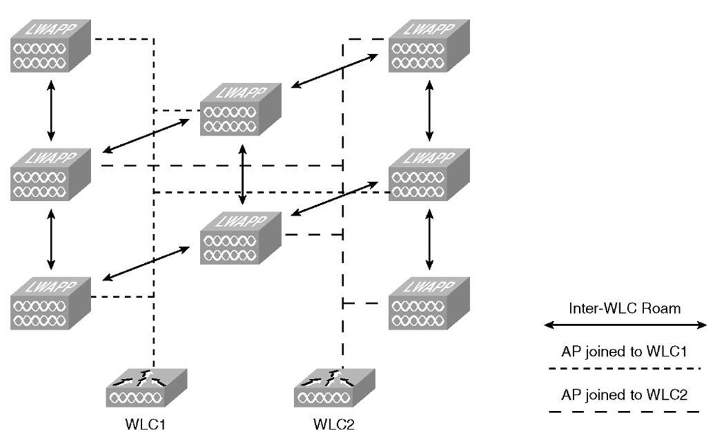
Another consideration is how to deploy the APs per controller on the network if you will have more than one. A common deployment is known as a salt-and-pepper or checkerboard deployment. With salt-and-pepper, the idea is that you have every other AP on the floor joined to a different controller, as shown in Figure 5-1. This physical deployment provides dynamic traffic load-balancing between the controllers and radio frequency (RF) resiliency. In the case of a single controller failure, only half of the APs on a particular floor would be lost; the remaining APs could still service the wireless clients.
Although salt-and-pepper sounds like a good idea in theory, it does have several drawbacks. With every other AP joined to a different controller, the number of inter-controller roaming events increases many-fold. As illustrated in Figure 5-1, almost every time a client roams, it roams to an AP joined to the other controller. Even though inter-controller roaming is highly optimized when you configure it correctly, intracon-troller roaming is more efficient. The aggressive load-balancing feature of the controller, if enabled, works on a per-controller basis, so a salt-and-pepper deployment would essentially defeat the feature. Troubleshooting client issues also becomes more difficult because it adds a layer of complexity.
Figure 5-1 Salt-and-Pepper Deployment
Client traffic patterns become unpredictable, which makes troubleshooting more difficult. Regardless of how the APs are dispersed across controllers in your network, should one controller fail, all clients associated to APs on the failed controller are disconnected. A salt-and-pepper design does not overcome this fundamental aspect of the CUWN, so you gain no high availability. Cisco does not recommend a salt-and-pepper deployment because, in addition to the reasons already stated, a failure in this scenario will result in the Radio Resource Management (RRM) feature performing harsh adjustments with the loss of the surrounding APs. Because the radios adjust power and channel, even though half of the APs did not drop, the clients will still be affected until the system settles under the new RF conditions. When the situation is cleared, the process will start again as the missing APs come back online.
A better solution is to separate the APs between the controllers into logical coverage areas such as by floor. In this case, should you have a controller or network failure that takes down one controller, you would only lose wireless on a particular floor(s) until the APs were able to join their secondary or backup controller.
Dense AP Deployment Considerations
Not every wireless deployment consists of placing APs on a floor to provide coverage to a dispersed number of clients. Conference rooms and convention centers pose a unique problem in that you have a concentrated client base in a confined space. Your AP placement and channel design must take this into account because here, even more than usual, the drawbacks of a half-duplex medium such as wireless are highlighted.
In the 2.4-GHz band, you have only three nonoverlapping channels: 1, 6, and 11. This limitation creates unique design constraints for a dense deployment because you need to mitigate co-channel interference while still providing adequate coverage for the users. As the number of clients increases, the majority of the co-channel interference will be caused by the clients sending and receiving packets on the same channel.
Although you can have up to 254 clients associated with a single AP (128 per radio if AP has both b/g and a radio), because wireless is half-duplex, a single 802.11b client can only realize about 5.6 Mbps throughput at best. For 802.11g or 802.11a only, a client can realize only around 28 Mbps. If you are mixing 802.11b and 802.11g clients, the 802.11g clients are forced to use protection mechanisms that essentially cut the throughput in half. You also need to consider the type of client traffic you are expecting. The situation is much different for clients just surfing the web as opposed to 200 clients trying to download MP3 files at the same time. Cisco recommends designing the network for no more than 40-50 users per AP in an auditorium-like environment. You can place the APs as close as to within 6 feet of each other. APs on the same channel should be as far apart from each other as you can manage.
To help mitigate co-channel interference and improve performance, you would ideally disable all the data rates below 12 Mbps. The majority of wireless clients these days are 802.11g compliant, and the newest are usually 802.11a compliant as well. Disabling the lower data rates prevents 802.11b clients from connecting and causes the 802.11g clients to initiate the protection mechanisms. The protection mechanisms cause the 802.11g clients to send Request To Send (RTS) and Clear To Send (CTS) messages so the 802.11b clients know if the channel is in use. The clients send RTS/CTS frames at the slowest supported rate in addition to the beacon frames. The additional traffic at the slowest rate further degrades the efficiency of the channel. If you know you will have 802.11b clients, only enable the 11-Mbps data rate and set it to Mandatory/Basic.
Disabling the lower data rates also means that you have less cell coverage by each AP, so co-channel overlap is reduced. In addition, it means that the radios use the channel less for beaconing. An AP radio can send more than 5 times the number of 100-byte beacons at 11 Mbps than it can at 1 Mbps. Table 5-1 shows the comparison of data rates and beacon size and how long the radio occupies the channel in microseconds to send it.
Note The values listed in Table 5-1 are for the beacon only. The PHY header is an additional 100 microseconds. Because of this, when you have multiple WLANs, the transmission time is multiplied. Therefore, if you have four WLANs, it increases the transmission time by a factor of four.
Table 5-1 Beacon Transmission Times (Microseconds) Versus Data Rate
|
802.11b |
|
|
Beacon Size |
||
|
100 |
200 |
250 |
300 |
350 |
|
|
Data Rate (Mbps) |
|||||
|
1 |
896 |
1696 |
2096 |
2496 |
2896 |
|
2 |
496 |
896 |
1096 |
1296 |
1496 |
|
5.5 |
241 |
387 |
460 |
532 |
605 |
|
11 |
169 |
241 |
278 |
314 |
351 |
|
802.11a/g/n |
Beacon Size |
||||
|
100 |
200 |
250 |
300 |
350 |
|
|
Data Rate (Mbps) |
|||||
|
6 |
153 |
287 |
353 |
420 |
487 |
|
12 |
87 |
153 |
187 |
220 |
253 |
|
24 |
53 |
87 |
103 |
120 |
137 |
|
54 |
35 |
50 |
57 |
64 |
72 |
|
130 |
26 |
32 |
35 |
38 |
42 |
|
300 |
23 |
25 |
27 |
28 |
29 |
Having higher data rates means the radio uses the channel less often and decreases the cell size. In most cases, this improves client roaming.
When designing a dense AP deployment, Cisco recommends using the 5-GHz band. Unlike the 2.4-GHz range where you are limited to only three nonoverlapping channels, the 5-GHz band has 21 nonoverlapping channels. Having more channels to use can mean that no two APs have to use the same channel, which greatly reduces co-channel interference. If you needed to place more than 21 APs, you could really increase the physical distance between APs on the same channel.
Most new wireless supplicants that support the 5-GHz band try to associate using a 5GHz channel first and only try using b/g if all the 5-GHz channels fail. If the client supports this feature, it helps keep 802.11a capable clients from using the 802.11g channels and helps minimize channel usage on channels 1, 6, and 11.
Note An upcoming controller code release allows the APs to aid in steering wireless clients that are 802.11a capable toward the 5-GHz radio.
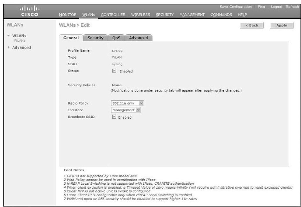
If you know you will only have 802.11a clients or you want to prevent any non-802.11a clients from associating to a particular WLAN, you can always use the Radio Policy feature and limit the WLAN to 5 GHz. You can also use this feature to limit a WLAN to just 802.11g, 802.11a/g, or 802.11b/g clients. Figure 5-2 shows the Radio Policy limiting the WLAN to 802.11a.
Figure 5-2 WLAN Radio Policy Feature
When designing an 802.11a network, you need to be aware that the controller automatically enables Dynamic Frequency Selection (DFS) on 15 channels (52-140). If an AP detects radar on the channel it is currently using, it scans for a new channel and waits 60 seconds to make sure no radar is on that channel before it starts using it. An AP does not try to use the previous channel again for 30 minutes. Even if you hard-code the AP channel and do not use Auto-RF, the AP must change channels when radar is detected. This is a key point when designing the network. If you have a sparse AP deployment and an AP detects radar and changes channels, your clients may not have another AP they can roam to. If not, the client experiences a significant loss of service until the original AP selects another channel and stars servicing those clients again.
802.11n
Another design consideration is the new 802.11n Standard Client devices that support 802.11n can achieve data rates up to 144 Mbps on the 2.4-GHz band and 300 Mbps on the 5-GHz band. Cisco currently offers two AP models that support 802.11n: the 1140 and 1250 series APs. The coverage of these APs is almost identical to the non-802.11n APs such as the 1242 AP. This means transitioning from legacy deployments should be fairly painless based on RF coverage. As with any wireless deployment, however, you should perform a site survey to determine proper AP density and placement. Designing an 802.11n network is similar to designing a legacy wireless network, but you need to take other considerations into account.
If you want to provide the highest N data rates, you have to use channel bonding. With channel bonding, you aggregate two channels to get increased bandwidth. Bonding two channels means you cut the number of non-overlapping channels to one for 2.4 GHz and nine for 5 GHz. Cisco only recommends using channel bonding on the 5-GHz band because you essentially wreck the 2.4-GHz band if you use channel bonding.
Another issue is power. To fully realize the 802.11n rates, the APs require a little more power than standard APs. A 1250 series AP requires 18.5W, and the 1140 series needs 12.95W Regular 802.3af PoE switches can provide a maximum of 15.4W, so if you are planning to use 1250 series APs, the switch would not be able to fully power the unit. You need to use a local power supply or a power injector to fully power the AP. This can affect the physical placement of your APs.
The physical port speed of your switch is another factor. Although the 802.11n APs support 10/100/1000 Mbps, you can create a bottleneck at the switch port if you connect the AP to a 10- or 100-Mbps port. This logic also applies to the 2100 series controllers. The network ports on those controllers are only 10/100. You can imagine the bottleneck of a 2125 with 25 1250 series APs and hundreds of 802.11n clients all trying to pass traffic through a 100-Mbps port.
Just as 802.11g uses protection mechanisms to allow for backward compatibility with older clients, 802.11n uses protection to allow for non-11n clients to associate and use the wireless medium. Also just like 802.11g, the coexistence with legacy clients lowers the performance of the 802.11n network compared to an 11n-only network. Despite the resulting lower throughput, the overall throughput is much higher than the older standards.
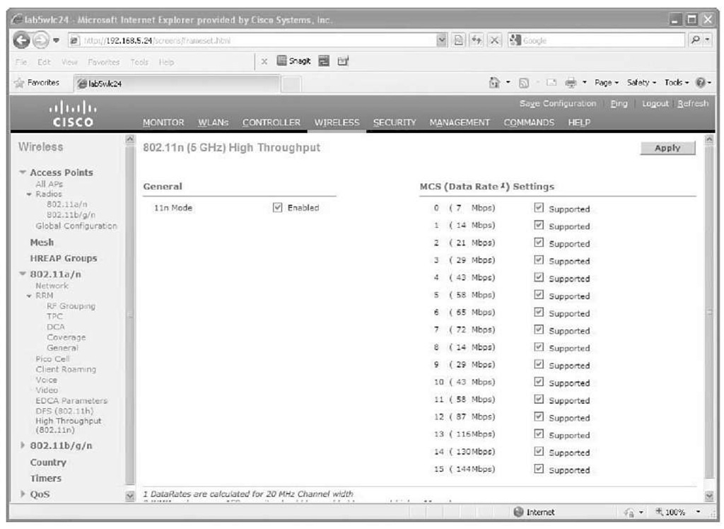
Finally, in addition to channel bonding, a controller needs to have the correct configuration to support 802.11n clients. The 802.11n mode must be enabled, as illustrated in Figure 5-3.
Also, the WLAN that the 802.11n clients use must have the correct security and quality of service (QoS) enabled. The 802.11n Standard requires either no security or WPA2 with Advanced Encryption Standard (AES) encryption. It also requires that Wi-Fi Multimedia (WMM) be allowed or required.If you have legacy clients that cannot use WPA2/AES, you need to plan accordingly and either create a separate WLAN for those clients or perhaps even remove those clients from the network.
Figure 5-3 Enabling 802.11n Mode
Location Design Considerations
The Cisco Wireless Location Appliance and the new, more powerful Mobility Services Engine (MSE) aggregate client information from the APs on the controllers to track locations of wireless devices. A single Location Appliance can track up to 2500 individual devices, including legitimate wireless clients, rogue clients, rogue APs, and radio frequency identification (RFID) tags. The 3350 MSE can track up to 18,000 devices, 3,000 Monitor Mode APs, and its Mobile Intelligent Roaming software supports up to 2,000 registered devices simultaneously. Although the Location Appliance and MSE are outside the scope of this topic, it is important to understand the design considerations that a location-based deployment requires.
Cisco advertises accuracy within 30 feet (10 m) 90 percent of the time when using the Location Appliance. The more APs that hear a wireless device, the better the location accuracy is going to be. You want to ensure that no fewer than three APs, and preferably four or five, provide coverage to every area where device location is required.
Make sure these two important guidelines are adhered to, listed in order of priority:
1. Access points should surround the desired location.
2. One access point should be placed roughly every 50 to 70 linear feet (about 17 to 20 meters). This translates into one access point every 2500 to 5000 square feet (about 230 to 450 square meters).
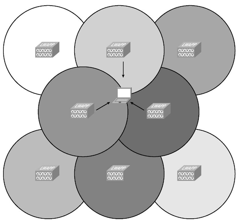
You should place APs around the periphery of the environment to help locate devices close to outside walls. Staggering APs within the interior as well as the periphery greatly improve location accuracy, as illustrated in Figure 5-4.
Figure 5-4 Location Deployment AP Placement
In Figure 5-4, three APs hear the client, which aids in triangulating the client and provides much more accurate location results.
Using directional antennas on the APs along the walls also helps by keeping the wireless signal within the building.
Note Devices must be detected at signals greater than -75 dBm for the controllers to forward information to the location appliance or MSE. No fewer than three access points should be able to detect any device at signals below -75 dBm.
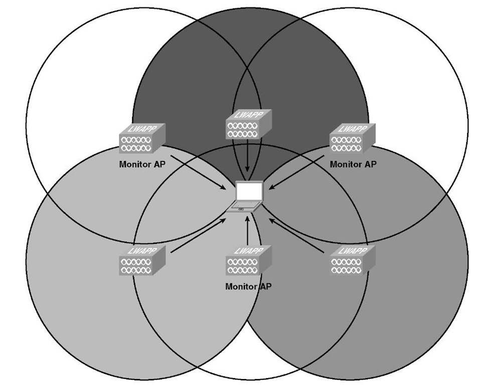
As you already know, dense deployments pose unique design and RF considerations. Should you have both voice and data clients, a dense deployment of APs can actually hinder the voice clients because the phones hear too many APs and are not able to make good roaming decisions. To have a deployment that satisfies the requirements for good location accuracy and allows your wireless phones to operate optimally, you can place APs in Monitor mode throughout the network, as illustrated in Figure 5-5.
Figure 5-5 Using Monitor Mode APs
In Figure 5-5, the client device is heard by all six APs, but it can only associate with the non-Monitor Mode APs. An AP in Monitor Mode does not service wireless clients (clear RF circles); therefore, it is not considered when a client is roaming or trying to associate with a WLAN. Monitor APs act as dedicated sensors for the location-based services (LBS), such as rogue AP detection and IDS. When the APs are in Monitor Mode, they can only receive; therefore, they cannot service clients or attach to suspected rogue APs they detect. A Monitor AP scans through every configured channel once every 12 seconds.
With this design, you have a high AP density, which is good for location services, but because only half of the APs actually service wireless clients, the density is not too high for a voice deployment.
Perhaps the worst possible AP placement for location is if the APs are in a straight line, as illustrated in Figure 5-6.
Figure 5-6 Linear AP Placement
Although the AP placement in Figure 5-6 provides plenty of wireless coverage, the location algorithm suffers dramatically because a single AP hears the client device. If two APs hear the client, the location algorithms have no way of telling whether the devices are above or below the AP.
Summary
When designing your wireless controller installation, you need to understand all the different factors that affect the performance of the system. You need to understand the different controller models and their features to make sure they meet your design goals. You also need to understand the physical placement of the controller and the APs within the network and how that affects traffic flow between the APs and the controller. Are you planning for a conference that services thousands of clients or just provides wireless access for a remote office with five employees? You also need to consider the network itself; what type of bandwidth do you have at your disposal, and is there an inherent delay that might warrant placing a controller locally at a particular site, using H-REAP, or simply installing a standalone AP(s)? Understanding the capabilities of your wireless clients allows you to design your network to best service those clients. Putting all of that together aids you in designing a stable and usable wireless infrastructure.
