The past few years have seen radical changes in the backbone, both in terms of new technologies (e.g., gigabit Ethernet) and in architectures (e.g., switched backbones, VLANs). Ten years ago, the most common backbone architecture was the routed backbone, connected to a series of shared 10Base-T hubs in the LAN.
Today, the most effective architecture for the distribution layer in terms of cost and performance is a switched backbone (either rack-mounted or using a chassis switch) because it provides the best performance at the least cost. For the core layer, most organizations use a routed backbone. Many large organizations are now implementing VLANs, especially those which have departments spread over multiple buildings, but VLANs add considerable cost and complexity to the network.
Moving to Gigabit Ethernet
MANAGEMENT FOCUS
The amount of network traffic at university campuses has exploded over the last few years. This was especially true at the University of Essex. The university was running an FDDI ring as its core backbone that connected to six FDDI distribution layer backbones covering the various administrative and academic departments at the university. This backbone supported approximately 3,800 computers, most of which were located on switched 10Base-T and 10/100 switched LANs, although a few LANs still ran legacy 10Base-2 and shared 10Base-T LANs.
The problem was that the FDDI rings could not be increased from the standard 100 Mbps although traffic had pushed them to the breaking point. So the decision was made to replace the FDDI backbones with gigabit Ethernet.
The new network features a collapsed backbone with a series of 10/100 switches supporting the LANs, each with a fiber-optic gigabit Ethernet connection into a central core router. The new architecture permits the introduction of VLANs, QoS priority queuing, and IGMP multicast filtering, as well as enabling the development of improved security and management facilities.
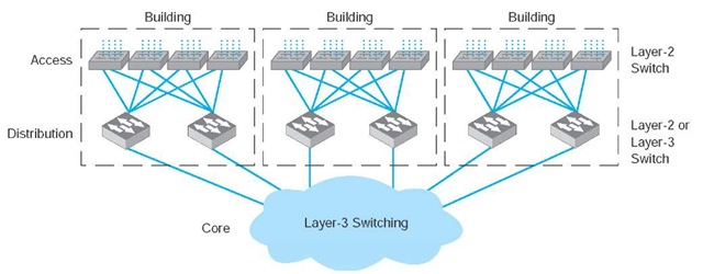
Given the trade-offs in costs, there are several best practice recommendations. First, the best practice architecture is a switched backbone or VLAN for the distribution layer and a routed backbone for the core layer. Second, the best practice recommendation for backbone technology is gigabit Ethernet. Considering the LAN and backbone environments together, the ideal network design is likely to be a mix of layer-2 and layer-3 Ethernet switches. Figure 8.15 shows one likely design. The access layer (i.e., the LANs) uses 100Base-T layer-2 Ethernet switches running on cat 5e or cat 6 twisted-pair cables to provide flexibility for 100Base-T or 1000Base-T. The distribution layer uses layer-2 or layer-3 Ethernet switches that use 100Base-T or more likely 1000Base-T/F (over fiber or cat 6) to connect to the access layer. To provide good reliability, some organizations may provide redundant switches, so if one fails, the backbone continues to operate. The core layer uses layer-3 Ethernet switches running 10 GbE or 40 GbE over fiber.
Figure 8.15 The best practice network design
Multiprotocol Label Switching
TECHNICAL FOCUS
Multiprotocol Label Switching (MPLS) is an approach to improving QoS and the movement of packets with different layer-2 protocols through TCP/IP networks.
With MPLS, routers called Label Switched Routers (LSRs) are used. The network manager defines a series of Forwarding Equivalence Classes (FEC) through the network of LSRs. Each FEC has a reserved data rate and a QoS.
When a packet arrives at the edge of the MPLS network, an edge LSR reads the destination address on the incoming packet. The edge LSR can be configured to use the IP address, the IP address and the source or destination port, or the address in any protocol understood by the LSR. The edge LSR accepts the incoming packet and attaches an MPLS label (a packet that contains the FEC address). The edge LSR then forwards the packet to the next LSR as defined in the FEC.
This LSR reads the MPLS label and removes it from the incoming packet, consults its MPLS address table to find the packet’s next destination, attaches a new MPLS label with the new FEC address, and forwards the packet to the next LSR in the FEC.
This process continues until the packet reaches the edge LSR closest to its final destination. This edge LSR strips off the MPLS label and forwards the packet outside of the MPLS network in exactly the same format in which it entered the MPLS network.
The advantage of MPLS is that it can easily integrate layer-2 protocols and also provide QoS in an IP environment. It also enables traffic management by enabling the network manager to specify FEC based on both the IP address and the source or destination port.

