This topic has discussed the functions of the transport and network layers: linking to the application layer, segmenting, session management, addressing, and routing. In this section, we tie all of these concepts together to take a closer look at how these functions actually work using TCP/IP.
When a computer is installed on a TCP/IP network (or dials into a TCP/IP network), it must be given four pieces of network layer addressing and routing information before it can operate. This information can be provided by a configuration file, or via a DHCP server. The information is
1. Its IP address
2. A subnet mask, so it can determine what addresses are part of its subnet
3. The IP address of a DNS server, so it can translate application layer addresses into IP addresses
4. The IP address of an IP gateway (commonly called a router) leading outside of its subnet, so it can route messages addressed to computers outside of its subnet (this presumes the computer is using static routing and there is only one connection from it to the outside world through which all messages must flow; if it used dynamic routing, some routing software would be needed instead)
These four pieces of information are the minimum required. A server would also need to know its application layer address.
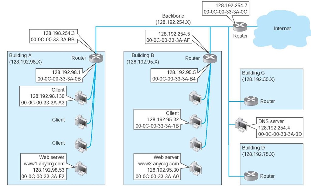
In this section, we use the simple network shown in Figure 5.13 to illustrate how TCP/IP works. This figure shows an organization that has four LANs connected by a BN. The BN also has a connection to the Internet. Each building is configured as a separate subnet. For example, Building A has the 128.192.98.x subnet, whereas Building B has the 128.192.95.x subnet. The BN is its own subnet: 128.192.254.x. Each building is connected to the BN via a router that has two IP addresses and two data link layer addresses, one for the connection into the building and one for the connection onto the BN. The organization has several Web servers spread throughout the four buildings. The DNS server and the router onto the Internet are located directly on the BN itself. For simplicity, we will assume that all networks use Ethernet as the data link layer and will only focus on Web requests at the application layer.
In the sections below, we describe how messages are sent through the network. For the sake of simplicity, we will initially ignore the need to establish and close TCP connections. Once you understand the basic concepts, we will then add these in to complete the example.
Figure 5.13 Example Transmission Control Protocol/Internet Protocol (TCP/IP) network
Finding Your Computer’s tcp/ip Settings
TECHNICAL FOCUS
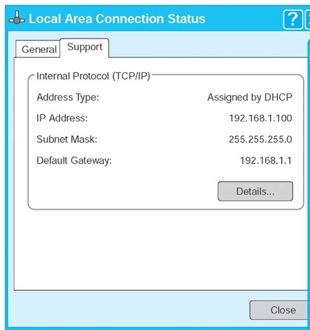
If your computer can access the Internet, it must use TCP/IP. In Windows, you can find out your TCP/IP settings by looking at their properties. Click on the Start button and then select Control Panel and then select Network Connections. Double click on your Local Area Connection and then click the Support tab.
This will show you your computer’s IP address, subnet mask, and gateway, and whether the IP address is assigned by a DHCP server. Figure 5.14 shows this information for one of our computers.
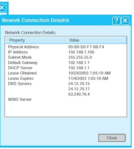
If you would like more information, you can click on the Details button. This second window shows the same information, plus the computer’s Ethernet address (called the physical address), as well as information about the DHCP lease and the DNS servers available.
Try this on your computer. If you have your own home network with your own router, there is a chance that your computer has an IP address very similar to ours or someone else’s in your class —or the same address, in fact. How can two computers have the same IP address? Well, they can’t. This is a security technique called network address translation in which one set of ”private” IP addresses is used inside a network and a different set of ”public” IP addresses is used by the router when it sends the messages onto the Internet.
FIGURE 5.14 TCP/IP configuration information
Known Addresses, Same Subnet
Let’s start with the simplest case. Suppose that a user on a client computer in Building A (128.192.98.130) requests a Web page from the Web server in the same building (www1.anyorg.com). We will assume that this computer knows the network layer and data link layer addresses of the Web server (e.g., it has previously requested pages from this server, so the addresses are in its address tables). Because the application layer software knows the IP address of the server, it uses its IP address, not its application layer address.
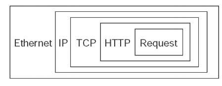
In this case, the application layer software (i.e., Web browser) passes an HTTP packet containing the user request to the transport layer software requesting a page from 128.192.98.53. The transport layer software (TCP) would take the HTTP packet, add a TCP segment, and then hand it to the network layer software (IP). The network layer software will compare the destination address (128.192.98.53) to the subnet mask (255.255.255.0) and discover that this computer is on its own subnet. The network layer software will then search its data link layer address table and find the matching data link layer address (00-0C-00-33-3A-F2). The network layer would then attach an IP packet and pass it to the data link layer, along with the destination Ethernet address. The data link layer would surround the frame with an Ethernet frame and transmit it over the physical layer to the Web server (Figure 5.15).
The data link layer on the Web server would perform error checking before passing the HTTP packet with the TCP segment and IP packet attached to its network layer software. The network layer software (IP) would then process the IP packet, see that it was destined to this computer, and pass it to the transport layer software (TCP). This software would process the TCP segment, see that there was only one packet, and pass the HTTP packet to the Web server software.
The Web server software would find the page requested, attach an HTTP packet, and pass it to its transport layer software. The transport layer software (TCP) would break the Web page into several smaller segment, each less than 1,500 bytes in length, and attach a TCP segment (with a number to indicate the order) to each. Each smaller segment would then go to the network layer software, get an IP packet attached that specified the IP address of the requesting client (128.192.98.130), and be given to the data link layer with the client’s Ethernet address (00-0C-00-33-3A-A3) for transmission. The data link layer on the server would transmit the frames in the order in which the network layer passed them to it.
Figure 5.15 Packet nesting. HTTP = Hypertext Transfer Protocol; IP = Internet Protocol; TCP = Transmission Control Protocol
The client’s data link layer software would receive the frames, perform error checking, and pass the IP packets inside them to the network layer. The network layer software (IP) would check to see that the packets were destined for this computer and pass the TCP segments they contained to the transport layer software. The transport layer software (TCP) would assemble the separate segments, in order, back into one Web page, and pass the HTTP packet in turn to the Web browser to display on the screen.
Known Addresses, Different Subnet
Suppose this time that the same client computer wanted to get a Web page from a Web server located somewhere in Building B (www2.anyorg.com). Again, assume that all addresses are known and are in the address tables of all computers. In this case, the application layer software would pass an HTTP packet to the transport layer software (TCP) with the Internet address of the destination www2.anyorg.com: 128.192.95.30. The transport layer software (TCP) would make sure that the request fit in one segment and hand it to the network layer. The network layer software (IP) would then check the subnet mask and would recognize that the Web server is located outside of its subnet. Any messages going outside the subnet must be sent to the router (128.192.98.1), whose job it is to process the message and send the message on its way into the outside network. The network layer software would check its address table and find the Ethernet address for the router. It would therefore set the data link layer address to the router’s Ethernet address on this subnet (00-0C-00-33-3A-0B) and pass the IP packet to the data link layer for transmission. The data link layer would add the Ethernet frame and pass it to the physical layer for transmission.
The router would receive the message and its data link layer would perform error checking and send an acknowledgement before passing the packet to the network layer software (IP). The network layer software would read the IP address to determine the final destination. The router would recognize that this address (128.192.95.30) needed to be sent to the 128.192.95.x subnet. It knows the router for this subnet is 128.192.254.5. It would pass the packet back to its data link layer, giving the Ethernet address of the router (00-0C-00-33-3A-AF).
This router would receive the message (do error checking, etc.) and read the IP address to determine the final destination. The router would recognize that this address (128.192.95.30) was inside its 128.192.95.x subnet and would search its data link layer address table for this computer. It would then pass the packet to the data link layer along with the Ethernet address (00-0C-00-33-3A-A0) for transmission.
The www2.anyorg.com web server would receive the message and process it. This would result in a series of TCP/IP packets addressed to the requesting client (128.192.98.130). These would make their way through the network in reverse order. The Web server would recognize that this IP address is outside its subnet and would send the message to the 128.192.95.5 router using its Ethernet address (00-0C-00-33-3A-B4). This router would then send the message to the router for the 128.192.98.x subnet (128.192.254.3) using its Ethernet address (00-0C-00-33-3A-BB). This router would in turn send the message back to the client (128.192.98.130) using its Ethernet address (00-0C-00-33-3A-A3).
This process would work in the same way for Web servers located outside the organization on the Internet. In this case, the message would go from the client to the 128.192.98.x router, which would send it to the Internet router (128.192.254.7), which would send it to its Internet connection. The message would be routed through the Internet, from router to router until it reached its destination. Then the process would work in reverse to return the requested page.
Unknown Addresses
Let’s return to the simplest case (requesting a Web page from a Web server on the same subnet), only this time we will assume that the client computer does not know the network layer or data link layer address of the Web server. For simplicity, we will assume that the client knows the data link layer address of its subnet router, but after you read through this example, you will realize that obtaining the data link layer address of the subnet router is straightforward. (It is done the same way as the client obtains the data link layer address of the Web server.)
Suppose the client computer in Building A (128.192.98.130) wants to retrieve a Web page from the www1.anyorg.com Web server but does not know its addresses. The Web browser realizes that it does not know the IP address after searching its IP address table and not finding a matching entry. Therefore, it issues a DNS request to the name server (128.192.254.4). The DNS request is passed to the transport layer (TCP), which attaches a UDP datagram and hands the message to the network layer.
Using its subnet mask, the network layer (IP) will recognize that the DNS server is outside of its subnet. It will attach an IP packet and set the data link layer address to its router’s address.
The router will process the message and recognize that the 128.192.254.4 IP address is on the BN. It will transmit the packet using the DNS server’s Ethernet address.
The name server will process the DNS request and send the matching IP address back to the client via the 128.198.98.x subnet router.
The IP address for the desired computer makes its way back to the application layer software, which stores it in its IP table. It then issues the HTTP request using the IP address for the Web server (128.192.98.53) and passes it to the transport layer, which in turn passes it to the network layer. The network layer uses its subnet mask and recognizes that this computer is on its subnet. However, it does not know the Web server’s Ethernet address. Therefore, it broadcasts an ARP request to all computers on its subnet, requesting that the computer whose IP address is 128.192.98.53 to respond with its Ethernet address.
This request is processed by all computers on the subnet, but only the Web server responds with an ARP packet giving its Ethernet address. The network layer software on the client stores this address in its data link layer address table and sends the original Web request to the Web server using its Ethernet address.
This process works the same for a Web server outside the subnet, whether in the same organization or anywhere on the Internet. If the Web server is far away (e.g., Australia), the process will likely involve searching more than one name server, but it is still the same process.
TCP Connections
Whenever a computer transmits data to another computer, it must choose whether to use a connection-oriented service via TCP or a connectionless service via UDP. Most application layer software such as Web browsers (HTTP), e-mail (SMTP), FTP, and Telnet use connection-oriented services. This means that before the first packet is sent, the transport layer first sends a SYN segment to establish a session. Once the session is established, then the data packets begin to flow. Once the data are finished, the session is closed with a FIN segment.
In the examples above, this means that the first packet sent is really a SYN segment, followed by a response from the receiver accepting the connection, and then the packets as described above. There is nothing magical about the SYN and FIN segments, they are addressed and routed in the same manner as any other packets. But they do add to the complexity and length of the example.
A special word is needed about HTTP packets. When HTTP was first developed, Web browsers opened a separate TCP session for each HTTP request. That is, when they requested a page, they would open a session, send the single packet requesting the Web page, and close the session at their end. The Web server would open a session, send as many packets as needed to transmit the requested page, and then close the session. If the page included graphic images, the Web browser would open and close a separate session for each request. This requirement to open and close sessions for each request was time consuming and not really necessary. With the newest version of HTTP, Web browsers open one session when they first issue an HTTP request and leave that session open for all subsequent HTTP requests to the same server.
TCP/IP and Network Layers
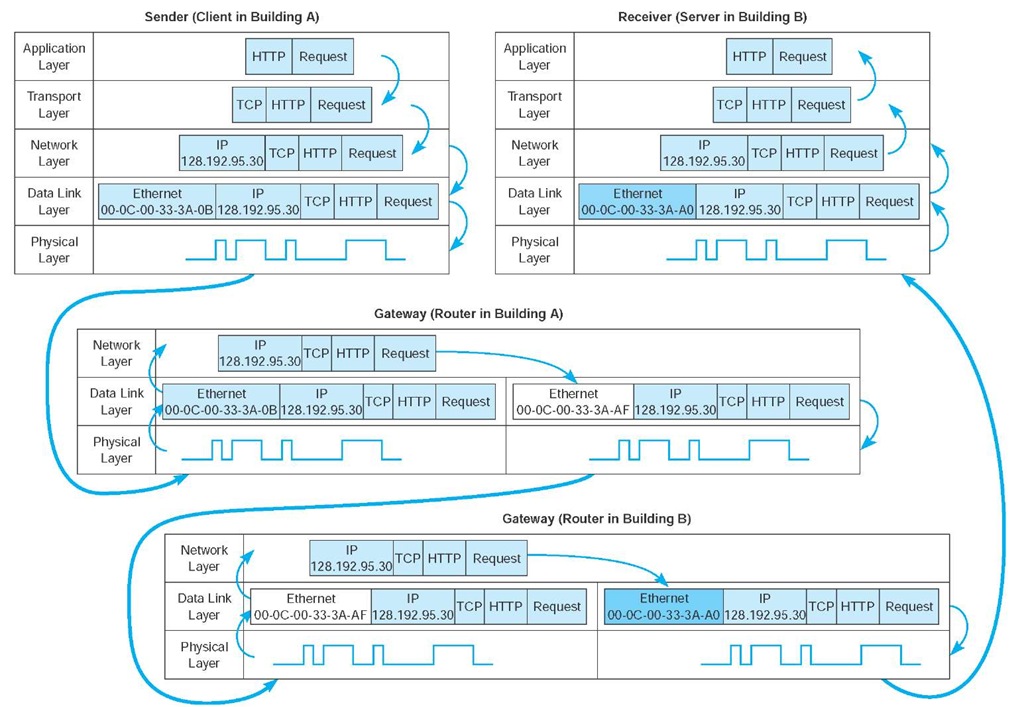
In closing this topic, we want to return to the layers in the network model and take another look at how messages flow through the layers. Figure 5.16 shows how a Web request message from a client computer in Building A would flow through the network layers in the different computers and devices on its way to the server in Building B.
The message starts at the application layer of the sending computer (the client in Building A), shown in the upper left corner of the figure, which generates an HTTP packet. This packet is passed to the transport layer, which surrounds the HTTP packet with a TCP segment. This is then passed to the network layer, which surrounds it with an IP frame that includes the IP address of the final destination (128.192.95.30). This in turn is passed to the data link layer, which surrounds it within an Ethernet frame that also includes the Ethernet address of the next computer to which the message will be sent (00-0C-00-33-3A-0B). Finally, this is passed to the physical layer, which converts it into electrical impulses for transmission through the cable to its next stop—the router that serves as the gateway in Building A.
FIGURE 5.16 How messages move through the network layers. Note: The addresses in this example are destination addresses
When the message arrives at the router in Building A, its physical layer translates it from electrical impulses into digital data and passes the Ethernet frame to the data link layer. The data link layer checks to make sure that the Ethernet frame is addressed to the router, performs error detection, strips off the Ethernet frame, and passes its contents (the IP packet) to the network layer. The routing software running at the network layer looks at the destination IP address, determines the next computer to which the packet should be sent, and passes the outgoing packet down to the data link layer for transmission. The data link layer surrounds the IP packet with a completely new Ethernet frame that contains the destination address of the next computer to which the packet will be sent (00-0C-00-33-3A-AF). In Figure 5.16, this new frame is shown in a different color. This is then passed to the physical layer, which transmits it through the network cable to its next stop—the router that serves as the gateway in Building B.
When the message arrives at the router in Building B, it goes through the same process. The physical layer passes the incoming packet to the data link layer, which checks the destination Ethernet address, performs error detection, strips off the Ethernet frame, and passes the IP packet to the network layer software. The software determines the next destination and passes the IP packet back to the data link layer, which adds a completely new Ethernet frame with the destination address of its next stop (00-0C-00-33-3A-A0)—its final destination.
The physical layer at the server receives the incoming packet and passes it to the data link layer, which checks the Ethernet address, performs error detection, removes the Ethernet frame, and passes the IP packet to the network layer. The network layer examines the final destination IP address on the incoming packet and recognizes that the server is the final destination. It strips off the IP packet and passes the TCP segment to the transport layer, which in turn strips off the TCP segment and passes the HTTP packet to the application layer (the Web server software).
There are two important things to remember from this example. First, at all gateways (i.e., routers) along the way, the packet moves through the physical layer and data link layer up to the network layer, but no higher. The routing software operates at the network layer, where it selects the next computer to which the packet should be sent, and passes the packet back down through the data link and physical layers. These three layers are involved at all computers and devices along the way, but the transport and application layers are only involved at the sending computer (to create the application layer packet and the TCP segment) and at the receiving computer (to understand the TCP segment and process the application layer packet). Inside the TCP/IP network itself, messages only reach layer three—no higher.
Podcasting
TECHNICAL FOCUS
Podcasting is the distribution of audio and video files (e.g., MP3 files) over the Internet. Podcasting uses a relatively old technology (first developed in 2000), but became popular with the introduction of Apple’s iPod.
Podcasting requires two things: the content and a channel description file that describes the content. The content is usually MP3 files, audio and/or video. Creating MP3 files is fairly straightforward — see the Hands-On Activity in next topic.
The channel description file describes the overall set of files, called a channel, as well as each individual MP3 file that is available. This file is an XML file that is created according to the RSS standard (RSS stands for Rich Site Summary, RDF Site Summary, or Really Simple Syndication, depending upon which version of the standard you read).
Users subscribe to a podcast channel by entering the URL of the channel description RSS file into their favorite aggregation software (e.g., iTunes). The aggregation software regularly reads the RSS file. When it notices that the RSS file contains a new entry for a new MP3 file, the software automatically downloads the new content to the user’s iPod.
Second, at each stop along the way, the Ethernet frame is removed and a new one is created. The Ethernet frame lives only long enough to move the message from one computer to the next and then is destroyed. In contrast, the IP packet and the packets above it (TCP and application layer) never change while the message is in transit. They are created and removed only by the original message sender and the final destination.
