Packet-switched networks are quite different from the two types of networks discussed previously. For both circuit-switched and dedicated-circuit networks, a circuit was established between the two communicating computers. This circuit provided a guaranteed data transmission capability that was available for use by only those two computers. For example, if computer A is to transmit data using an ISDN BRI connection to computer B, the connection at both A and B must be available. Once in use for this transmission, it is assigned solely to that transmission. No other transmission is possible until the circuit is closed.
Caregroup’s Dedicated Circuit Network
MANAGEMENT FOCUS
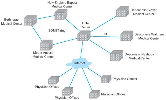
CareGroup Healthcare System operates six hospitals in the Boston area and uses a metropolitan area network (MAN) and wide area network to connect them together to share clinical data (Figure 9.8). The three major hospitals have relatively high data needs and therefore are connected to one another and the main data center via a MAN that uses a set of SONET OC-1 circuits in a ring architecture.
The other three hospitals, with lower data needs, ar connected to the data center via a set of T3 circuits in a star architecture. The data center also has a T3 connection into the Internet to enable its 3,000 or so doctors to access clinical data from their private practice offices or from home.
Figure 9.8 CareGroup’s metropolitan and wide area networks. SONET = synchronous optical network
So, for example, if computer C attempts to reach computer B, it will have to wait until the circuit is closed. In contrast, packet-switched services enable multiple connections to exist simultaneously between computers over the same physical circuit, just like LANs and BNs.
Basic Architecture
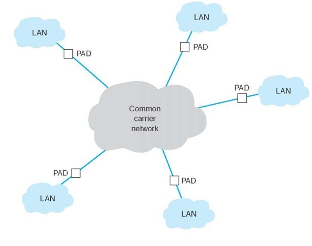
With packet-switched services, the user again buys a connection into the common carrier cloud (Figure 9.9). The user pays a fixed fee for the connection into the network (depending on the type and capacity of the service) and is charged for the number of packets transmitted.
The user’s connection into the network is a packet assembly/disassembly device (PAD), which can be owned and operated by the customer or by the common carrier. The PAD converts the sender’s data into the network layer and data link layer packets used by the packet network and sends them through the packet-switched network. At the other end, another PAD reassembles the packets back into the network layer and data link layer protocols expected by the destination and delivers it to the appropriate computer.
One of the key advantages of packet-switched services is that different locations can have different connection speeds into the common carrier cloud. The PAD compensates for differences in transmission speed between sender and receiver; for example, the circuit at the sender might be 1.5 Mbps whereas the receiver only has a 64-Kbps circuit. In contrast, a dial-up circuit or a dedicated circuit must have the same speed at both the sender and receiver.
Figure 9.9 Packet-switched services. LAN = local area network; PAD = packet assembly/disassembly device
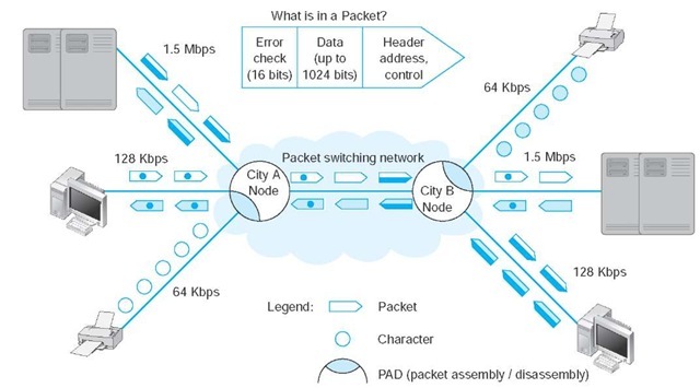
Packet-switched networks enable packets from separate messages with different destinations to be interleaved for transmission, unlike switched circuits and dedicated circuits. Packet switching is popular because most data communications consist of short bursts of data with intervening spaces that usually last longer than the actual burst of data. Packet switching takes advantage of this characteristic by interleaving bursts of data from many users to maximize use of the shared communication network. Figure 9.10 shows a packet-switching connection between six different cities. The little boat-shaped figures (shown on the communication circuits) represent individual packets from separate messages.
Although the packets in one data stream may mix with several other data streams during their journey, it is unlikely that packets from two different data streams will travel together during the entire length of their transmission. The two communicating computers do not need to know through which intermediate devices their data are routed because the packet network takes care of it by either of two methods.
The first method, called datagram, is a connectionless service. It adds a destination address and sequence number to each packet, in addition to information about the data stream to which the packet belongs. In this case, a route is chosen for each packet as it is accepted into the packet network. Each packet may follow a different route through the network. At the destination address, the sequence number tells the network how to reassemble the packets into a continuous message. The sequence number is necessary because different routes may deliver packets at different speeds, so data packets often arrive out of sequence. Few networks today use datagrams for data transfer.
The second and more common routing method is a connection-oriented approach called a virtual circuit. In this case, the packet-switched network establishes what appears to be one end-to-end circuit between the sender and receiver. All packets for that transmission take the same route over the virtual circuit that has been set up for that particular transmission. The two computers believe they have a dedicated point-to-point circuit, but in fact, they do not.
Figure 9.10 Packet-switching concepts
Virtual circuits are usually permanent virtual circuits (PVCs), which means that they are defined for frequent and consistent use by the network. They do not change unless the network manager changes the network. Some common carriers also permit the use of switched virtual circuits (SVCs) although this is not usual. Changing PVCs is done using software, but common carriers usually charge each time a PVC is established or removed. It often takes days or weeks to create or take down PVCs although this is mostly due to poor management by common carriers rather than due to technology issues, so this may change.
Because most network managers build packet-switched networks using PVCs, most packet-switched networks behave like dedicated-circuit networks. At first glance, the basic architecture in Figure 9.9 looks very similar to the cloud mesh of switched-circuit services, and in fact, they are very similar because data can move from any computer attached to the cloud to any other on the cloud. However, because virtually all data-intensive networks use PVCs, this means that the network is actually built using virtual circuits that are the software equivalent of the hardware-based dedicated circuits. As a result, packet-switched networks often have star, ring, and mesh topologies similar to those of dedicated-circuit networks. However, because the PVCs are in software, they are much easier to change than the hardware circuits of dedicated-circuit networks.
Most common carriers permit users to specify two different types of data rates that are negotiated per connection and for each PVC as it is established. The committed information rate (CIR) is the data rate the PVC must guarantee to transmit. If the network accepts the connection, it guarantees to provide that level of service. Most connections also specify a maximum allowable rate (MAR), which is the maximum rate that the network will attempt to provide, over and above the CIR. The circuit will attempt to transmit all packets up to the MAR, but all packets that exceed the CIR are marked as discard eligible (DE). If the network becomes overloaded, DE packets are discarded. So although users can transmit more data than the CIR, they do so at a risk of lost packets and the need to retransmit them.
Packet-switched services are often provided by different common carriers than the one from which organizations get their usual telephone and data services. Therefore, organizations often lease a dedicated circuit (e.g., T1) from their offices to the packet-switched network point of presence (POP). The POP is the location at which the packet-switched network (or any common carrier network, for that matter) connects into the local telephone exchange.
There are five types of packet-switched services: X.25, ATM, frame relay, switched multimegabit data service, and Ethernet service. Several common carriers (e.g., Sprint) have announced that they intend to stop offering all services except Ethernet and Internet services.Other carriers have hinted at the same decision. Over the next few years these technologies may disappear.
X.25
The oldest packet-switched service is X.25, a standard developed by ITU-T. X.25 offers datagram, SVC, and PVC services. X.25 uses the LAP-B data link layer protocol and the PLP network-layer protocol. When packets arrive at the PAD, connecting the user’s network to the packet-switched network, their data link (e.g., Ethernet) and network layer (e.g., IP) packets are removed and PLP and LAP-B packets are substituted. Packets are moved through the X.25 network in much the same way as in TCP/IP networks, with the LAP-B packet error checked and replaced at each hop in the network. When they arrive at the edge of the X.25 network, new destination protocols (e.g., Ethernet, IP) are created and the message is sent on its way. X.25 is sometimes called a reliable packet service because it provides complete error checking and guaranteed delivery on all packets transmitted.
Although common in Europe, X.25 is not widespread in North America. The primary reason is its transmission speed. For many years, the maximum speed into North American X.25 networks was 64 Kbps, but this has increased to 2.048Mbps, which is the European standard for ISDN. However, for many users, 2.048 Mbps is still not fast enough.
Asynchronous Transfer Mode
Asynchronous transfer mode (ATM), also standardized, is a newer technology than X.25. ATM for BNs was discussed in the previous topic. ATM for the MAN and WAN is essentially the same.
ATM is similar to X.25 in that it provides packet-switched services, but it has four distinct operating characteristics that differ from X.25. First, ATM performs encapsulation of packets, so packets are delivered unchanged through the network.
Second, ATM provides no error control in the network; error control is the responsibility of the source and destination. (ATM is considered an unreliable packet service.)
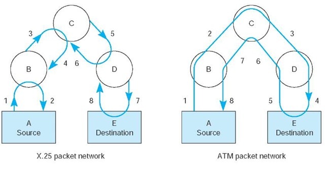
Figure 9.11 Asynchronous transfer mode (ATM) compared with X.25 packet switching. With X.25, each node sends an acknowledgment immediately on receiving a packet. With ATM, the final destination sends an acknowledgment, making this technique faster than the X.25 technique
Because the user’s data link packet remains intact, it is simple for the devices at the edge of the ATM network to check the error-control information in the packet to ensure that no errors have occurred and to request transmission of damaged or lost packets. Figure 9.11 illustrates the difference in error control between X.25 networks and ATM networks. The left side shows that when an X.25 packet leaves its source A and moves through node B, to node C, to node D, and finally to destination E, each intermediate node acknowledges the packet as it passes. The right side of the figure shows how an ATM packet moves through node B, node C, node D, and on to destination E. When destination E receives the packet correctly, a single acknowledgment is sent back through the nodes to source A, as shown by the numbers 5, 6, 7, and 8. Some common carriers have started using the term fast packet services instead to refer to these services that do not provide error control—it sounds better for marketing!
Third, ATM provides extensive QoS information that enables the setting of very precise priorities among different types of transmissions: high priority for voice and video, lower priority for e-mail.
Finally, ATM is scalable; it is easy to multiplex basic ATM circuits into much faster ATM circuits. Most common carriers offer ATM circuits that provide the same data transmission rates as SONET: 51.84 Mbps, 466.56 Mbps, 622.08 Mbps, and so on up to 39 Gbps (OC-768). New versions called T1 ATM (1.544 Mbps) and T3 ATM (45 Mbps) are also available.
Frame Relay
Frame relay, just recently standardized, is an even newer packet-switching technology that transmits data faster than X.25 but slower than ATM; it has sometimes been called a poor man’s ATM. It is one of the most commonly used WAN services in the world. Like ATM, frame relay performs encapsulation of packets, so packets are delivered unchanged through the network. Like ATM, it is an unreliable packet service because it does not perform error control. Frame relay checks for errors but simply discards packets with errors. It is up to the software at the source and destination to control for lost messages.
Frame relay does not yet provide QoS capabilities, but this is under development. Different common carriers offer frame relay networks with different transmission speeds.
Frame Relay in California
MANAGEMENT FOCUS
Ten communities in northern San Diego County, California, work together to provide fire department services to their citizens. The group spans 50 fire stations that needed to quickly and efficiently share voice, video, and computer data.
They implemented a converged frame relay network, using mostly T1 speed circuits (1.5 Mbps) into the frame relay network operated by AT&T. Each fire station has a PAD that connects their station’s voice and data network into the AT&T frame relay cloud. The PAD uses MPLS to tag all incoming IP packets with the PVC that leads to the destination address. As the packet leaves the frame relay network, the MPLS information is removed, and an Ethernet frame added for delivery into the destination station’s network.
Most offer a range of CIR speeds that include 56 Kbps, 128 Kbps, 256 Kbps, 384 Kbps, 1.5 Mbps, 2 Mbps, and 45 Mbps.
Ethernet Services
Although we have seen rapid increases in capacities and sharp decreases in costs in LAN and BN technologies, changes in MAN and WAN services offered by common carriers saw only modest changes in the 1990s. That changed in 2000 with the introduction of several Internet startups (e.g., Yipes) offering Ethernet services.
A Day in the Life: Networking and Telecommunications Vice President
A vice president is a person in an executive-level position whose focus is to set the strategic direction for the organization. A vice president has very little to do with the day-to-day operations; much like an Admiral in a Navy fleet, he or she defines the direction, but the individual captains running each ship actually make sure that everything that needs to happen gets done.
The vice president works with the chief information officer (CIO) and other executive leadership of the organization to identify the key organizational goals that have implications for the network. The vice president works with his or her staff to revise the strategic networking plan to ensure that the network is capable of supporting the organization’s goals. The key elements of the strategic plan are the networking architectures, key technologies, and vendors. Once the strategy has been set, the vice president’s job is to instruct the senior managers to execute the strategy and then let them do their jobs.
In most cases, the changes to the networking strategic plan are relatively minor, but sometimes there are dramatic changes that require a major shift in strategic direction. For example, in recent years, we’ve seen a major change in the fundamental capabilities of network tools and applications. Our architecture strategy during the 1990s was driven by the fact that network management tools were poor and maintenance costs per server were high; the fundamental architecture strategy was to minimize the number of servers. Today, network management tools are much better, maintenance costs per server are significantly lower, and network traffic has changed both in volume and in the number and complexity of services supported (e.g., Web, e-mail, H.323, IPv6); the strategy today is to provide a greater number of servers, each of which is dedicated to supporting one specific type of traffic.
Most organizations today use Ethernet and IP in the LAN and BN environment, yet the MAN/WAN packet network services (X.25, ATM, and frame relay) discussed earlier use different layer-2 protocols. Any LAN or BN traffic, therefore, must be translated or encapsulated into a new protocol and destination addresses generated for the new protocol. This takes time, slowing network throughput. It also adds complexity, meaning that companies must add staff knowledgeable in the different MAN/WAN protocols, software, and hardware these technologies require. This is one reason many common carriers are starting to call these four technologies "legacy technologies," signaling their demise.
Each of the preceding packet services uses the traditional PSTN provided by the common carriers such as AT&T and BellSouth. In contrast, Ethernet services bypass the PSTN; companies offering Ethernet services have laid their own gigabit Ethernet fiber-optic networks in large cities. When an organization signs up for service, the packet network company installs new fiber-optic cables from their citywide MAN backbone into the organization’s office complex and connects it to an Ethernet switch. The organization simply plugs its network into its Ethernet switch and begins using the service. All traffic entering the packet network must be Ethernet, using IP or MPLS.
Currently, Ethernet services offer CIR speeds of 1Mbps to 40 Gbps, in 1-Mbps increments at about one quarter the cost of traditional packet-switched networks. Because this is an emerging technology, we should see many changes in the next few years.


