There are many ways in which individuals and organizations can connect to an ISP. Some individuals use 56-Kbps dial-up modems over telephone lines; some use DSL or cable modem. As we discussed in the preceding section, many organizations lease T1 or T3 lines into their ISPs. DSL and cable modem technologies are commonly called broadband technologies because they provide higher-speed communications than traditional modems.1
It is important to understand that Internet access technologies are used only to connect from one location to an ISP. Unlike the MAN and WAN technologies in the previous topic, Internet access technologies cannot be used for general-purpose networking from any point to any point. In this section, we discuss four principal Internet access technologies (DSL, cable modem, fixed wireless, and mobile wireless) and also discuss some future technologies that may become common.
DSL
Digital subscriber line (DSL) is a family of point-to-point technologies designed to provide high-speed data transmission over traditional telephone lines.2 The reason for the limited capacity on traditional telephone circuits lies with the telephone and the switching equipment at the end offices. The actual cable in the local loop from a home or office to the telephone company end office is capable of providing much higher data transmission rates. So conversion from traditional telephone service (POTS) to DSL usually requires just changing the telephone equipment, not rewiring the local loop, which is what has made it so attractive.
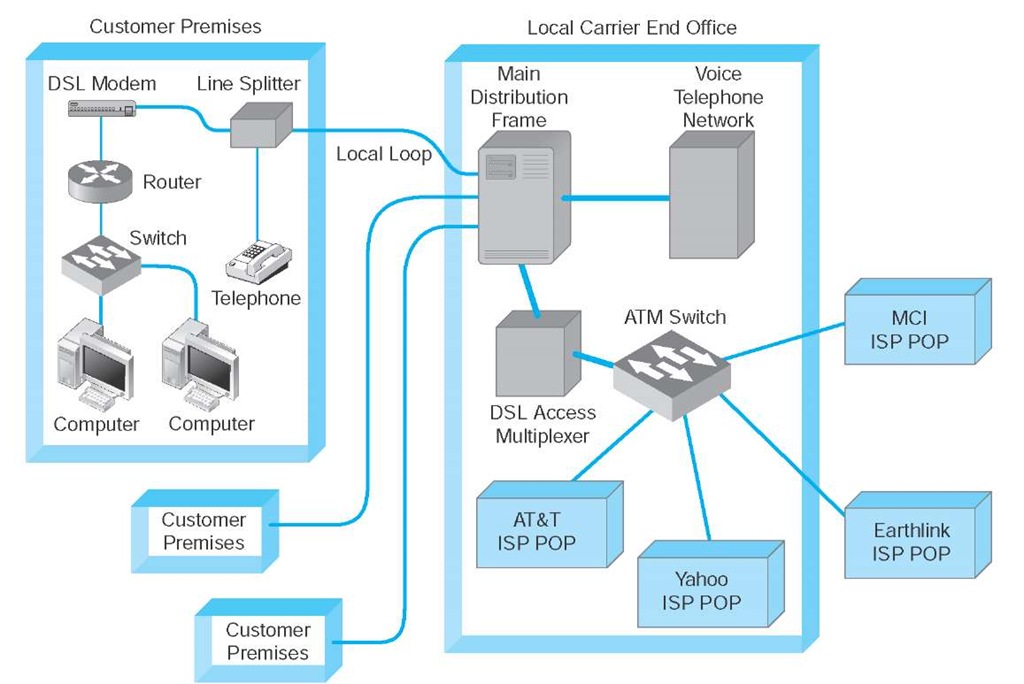
Architecture DSL uses the existing local loop cable but places different equipment on the customer premises (i.e., the home or office) and in the telephone company end office. The equipment that is installed at the customer location is called the customer premises equipment (CPE). Figure 10.5 shows one common type of DSL installation. (There are other forms.) The CPE in this case includes a line splitter that is used to separate the traditional voice telephone transmission from the data transmissions. The line splitter directs the telephone signals into the normal telephone system so that if the DSL equipment fails, voice communications are unaffected.
The line splitter also directs the data transmissions into a DSL modem, which is sometimes also called a DSL router. As you will recall from next topic, this is both a modem and an FDM multiplexer. The DSL modem produces Ethernet 10Base-T packets so it can be connected directly into a computer or to a router and hub and can serve the needs of a small network.
Figure 10.5 also shows the architecture within the local carrier’s end office (i.e., the telephone company office closest to the customer premises). The local loops from many customers enter and are connected to the main distribution facility (MDF). The MDF works like the CPE line splitter; it splits the voice traffic from the data traffic and directs the voice traffic to the voice telephone network and the data traffic to the DSL access multiplexer (DSLAM). The DSLAM de-multiplexes the data streams and converts them into ATM data, which are then distributed to the ISPs. Some ISPs are collocated, in that they have their POPs physically in the telephone company end offices. Other ISPs have their POPs located elsewhere.
Types of DSL DSL services are not available in all locations. In general, DSL services have advanced more quickly in Canada, Europe, Australia, and Asia than in the United States, owing to their newer telephone networks from the end offices to the customer.
Figure 10.5 Digital subscriber line (DSL) architecture. ATM = asynchronous transfer mode; ISP = Internet service provider; POP = point of presence
There are many different types of DSL. The most common type of DSL in use today is asymmetric DSL (ADSL). ADSL uses frequency division multiplexing to create three separate channels over the one local loop circuit. One channel is the traditional voice telephone circuit. A second channel is a relatively high-speed simplex data channel downstream from the carrier’s end office to the customer. The third channel is a slightly slower duplex data channel primarily used for upstream from the customer to the carrier’s end office.3 ADSL is called asymmetric because its two data channels have different speeds. Each of the two data channels are further multiplexed using time division multiplexing so they can be further subdivided.
The size of the two digital channels depends on the distance from the CPE to the end office. The shorter the distance, the higher the speed, because with a shorter distance, the circuit suffers less attenuation and higher-frequency signals can be used, providing a greater bandwidth for modulation. Figure 10.6 lists the common types of ADSL.
ADSL providers face a challenge in selecting what type of ADSL to offer in a given market. On one hand, customers want the highest speed access possible. However,because there is a trade-off between speed and distance, if an ADSL provider chooses a high-speed version, they have just limited the number of customers they can serve because a significant proportion of households in the United States are long distances from the nearest end office. Most ADSL providers have therefore chosen the T1 level of ADSL and offer it under the trademarked name of G.Lite ADSL. Higher speed versions are also available.
|
Type |
Maximum Length of Local Loop |
Maximum Downstream Rate |
Maximum Upstream Rate |
|
ADSL T1 (G.Lite) |
18,000 feet |
1.5 Mbps |
384 Kbps |
|
ADSL E1* |
16,000 feet |
2.0 Mbps |
384 Kbps |
|
ADSL T2 |
12,000 feet |
6 Mbps |
640 Kbps |
|
SDSL |
18,000 feet |
1.5 Mbps |
1.5 Mbps |
|
*E1 is the European standard services similar to T1 services in North America. |
|||
Figure 10.6 Digital subscriber line data rates
A second common type of DSL is very-high-data-rate digital subscriber line (VDSL). VDSL is asymmetric DSL service designed for use over very short local loops of at most 4,000 feet, with 1,000 feet being more typical. It also uses frequency division multiplexing (FDM) to provide three channels: the normal analog voice channel, an upstream digital channel, and a downstream digital channel. Figure 10.7 lists the types of VDSL we anticipate will become common.
VDSL has several standards that are in use. The exact data speeds and channels are likely to change as manufacturers, telephone companies, and ITU-T gain more experience and as the standards groups attempt to merge competing standards. Several companies are also developing symmetric versions of VDSL in which upstream and downstream channels have the same capacity. We expect major changes to VDSL.
Cable Modems
One alternative to DSL is the cable modem, a digital service offered by cable television companies. There are several competing standards, but the Data over Cable Service Interface Specification (DOCSIS) standard is the dominant one. DOCSIS is not a formal standard but is the one used by most vendors of hybrid fiber coax (HFC) networks (i.e., cable networks that use both fiber-optic and coaxial cable). As with DSL, these technologies are changing rapidly.4
|
Type |
Maximum Length of Local Loop |
Maximum Downstream Rate |
Maximum Upstream Rate |
|
1/4 OC-1 |
4,500 feet |
13 Mbps |
1.6 Mbps |
|
1/2 OC-1 |
4,000 feet |
26 Mbps |
2.3 Mbps |
|
OC-1 |
4,000 feet |
52 Mbps |
16 Mbps |
Figure 10.7 Data rates for very-high-data-rate digital subscriber line. OC = optical carrier
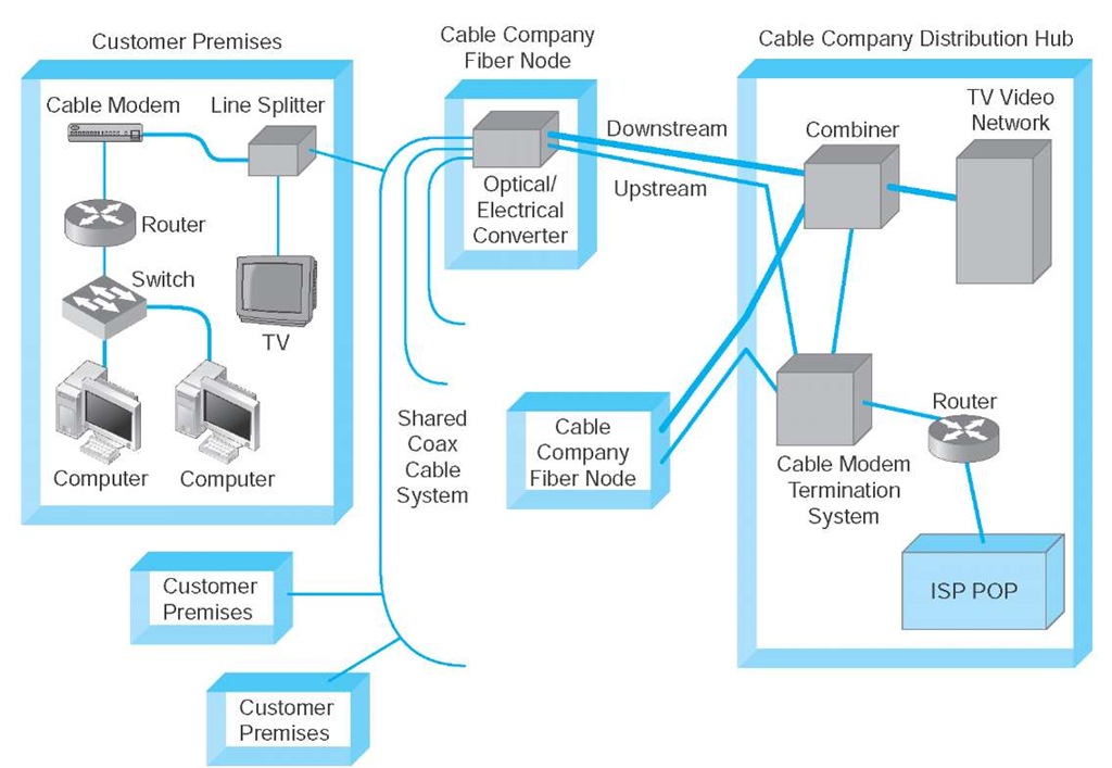
Architecture Cable modem architecture is very similar to DSL—with one very important difference. DSL is a point-to-point technology whereas cable modems use shared multipoint circuits. With cable modems, each user must compete with other users for the available capacity. Furthermore, because the cable circuit is a multipoint circuit, all messages on the circuit go to all computers on the circuit. If your neighbors were hackers, they could use pocket sniffers such as Ethereal to read all messages that travel over the cable, including yours.
Figure 10.8 shows the most common architecture for cable modems. The cable TV circuit enters the customer premises through a cable splitter that separates the data transmissions from the TV transmissions and sends the TV signals to the TV network and the data signals to the cable modem. The cable modem (both a modem and frequency division multiplexer) translates from the cable data into Ethernet packets,which then are directed into a computer to a router and hub for distribution in a small network.
Figure 10.8 Cable modem architecture. ISP = Internet service provider; POP = point of presence
The cable TV cable entering the customer premises is a standard coaxial cable. A typical segment of cable is shared by anywhere from 300 to 1,000 customers, depending on the cable company that installed the cable. These 300 to 1,000 customers share the available data capacity, but of course, not all customers who have cable TV will choose to install cable modems. This coax cable runs to a fiber node, which has an optical-electrical (OE) converter to convert between the coaxial cable on the customer side and fiber-optic cable on the cable TV company side. Each fiber node serves as many as half a dozen separate coaxial cable runs.
The fiber nodes are in turn connected to the cable company distribution hub (sometimes called a headend) through two separate circuits: an upstream circuit and a downstream circuit. The upstream circuit, containing data traffic from the customer, is connected into a cable modem termination system (CMTS). The CMTS contains a series of cable modems/multiplexers and converts the data from cable modem protocols into protocols needed for Internet traffic, before passing them to a router connected to an ISP POP. Often, the cable company is an Internet regional ISP, but sometimes it just provides Internet access to a third-party ISP.
The downstream circuit to the customer contains both ordinary video transmissions from the cable TV video network and data transmissions from the Internet. Downstream data traffic enters the distribution hub from the ISP POP and is routed through the CMTS, which produces the cable modem signals. This traffic is then sent to a combiner, which combines the Internet data traffic with the ordinary TV video traffic and sends it back to the fiber node for distribution.
Types of Cable Modems The DOCSIS standard provides many types of cable modems. The maximum speed is about 150 Mbps downstream and about 100 Mbps upstream, although most cable TV companies provide at most 27 Mbps downstream and 10 Mbps upstream. Cable modems can be configured to limit capacity, so the most common speeds offered by most cable providers range from 1-10 Mbps downstream and 256 Kbps to 1Mbps upstream. Of course, this capacity is shared, so an individual user will only see this when no other computers on his or her segment are active.
Fixed Wireless
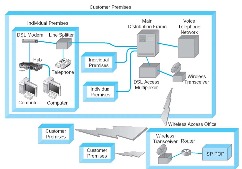
The most popular types of fixed wireless are WiMax and wireless DSL, which requires a line of sight between the communicating transmitters. For this reason, wireless DSL has limited application because it requires tall buildings or towers to be effective. The most common use today is to provide Internet access to multitenant buildings such as remote office buildings, apartment buildings, and hotels. Transmitters are used to connect the building to the ISP, and DSL is used inside the building to connect to the wireless transceiver (Figure 10.9).
WiMax may become a real competitor to wired Internet services such as cable modem and DSL because several large carriers have formed a new company (Clearwire) to offer 1.5 Mbps WiMax Internet services in major cities throughout the United States.
Internet Speed Test
MANAGEMENT FOCUS
The speed of your Internet connection depends upon many things, such as your computer’s settings, the connection from your computer to your ISP, and the connections your ISP has into the Internet. There are many Internet sites that enable you to test how fast your Internet connection actually is. Our favorite is speedtest.net.
Fixed wireless comes in both point-to-point and multipoint versions. The point-to-point version is designed to connect only two locations and is often used as backbone between buildings owned by the same organization. The multipoint version is sometimes called point-to-multipoint because there is one central receiver and all other locations communicate only with it. The multipoint version is designed as an alternative to DSL and cable modems and is intended for use by an ISP supporting a small number of customers. Like cable modems, the circuit is a shared circuit, so users must compete for the shared capacity, but most installations are limited to a few dozen users. Data transmission for both versions ranges from 1.5 to 54 Mbps, depending on the vendor.
Other fixed wireless technologies such as satellite are also available. Satellite technologies use the satellite for downstream transmissions (from the ISP to the customer) but use traditional dial-up modems for upstream transmissions.
Figure 10.9 Fixed wireless architecture. DSL = digital subscriber line; ISP = Internet service provider; POP = point of presence
Although satellite technology has been available for several years, it has never become really popular.
Mobile Wireless
Mobile wireless technologies enable users to access the Internet from any location where there is mobile wireless service. Widespread mobile wireless Internet access is probably the next major change in networking. Mobile wireless Internet access technologies exist today (e.g., cell phone connections), but most are slow compared with wired access, whether DSL, cable modem, or simply a dial-up modem. The WLAN technologies discussed in next topic (e.g., 802.11) are primarily intended for use inside one organization although they are also installed in public places such as coffee shops and airports for access to the Internet.
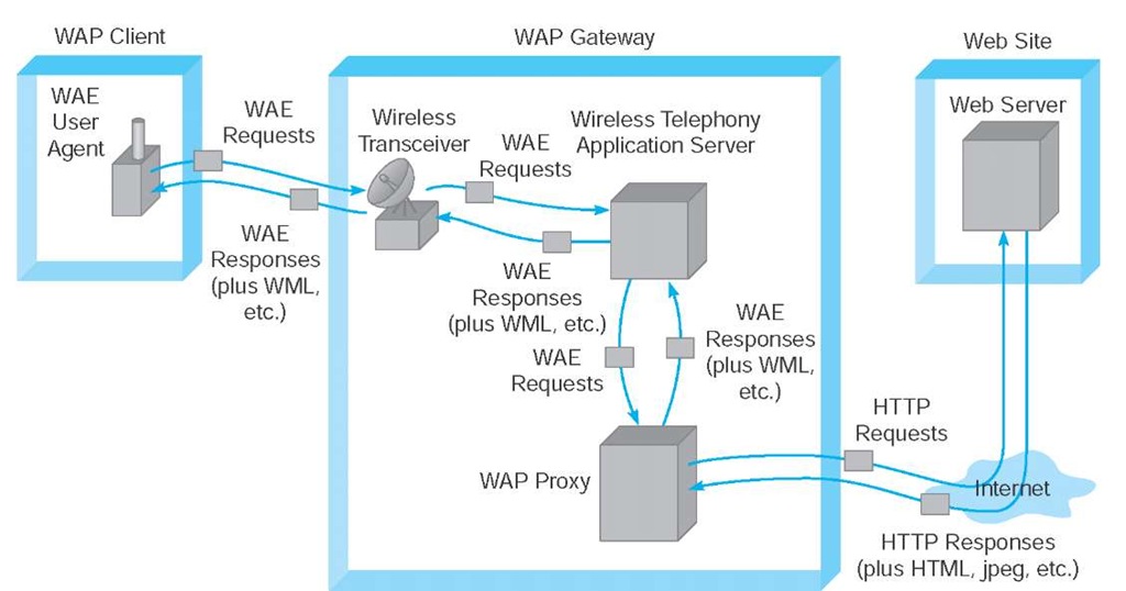
Wireless Application Protocol (WAP) provides a set of application and network protocols called the Wireless Application Environment (WAE) to support mobile wireless Internet applications. WAP is designed to enable the use of normal Web applications on computers and devices with small display screens operating over low-speed wireless connections. Figure 10.10 shows the basic WAP architecture.
The WAP client (a mobile phone, palm computer, or laptop computer) runs special WAP software called a WAE user agent. This software generates WAE requests that are similar in many ways to HTTP requests and transmits them wirelessly to a WAP gateway. A transceiver at the WAP gateway passes the requests to a wireless telephony application (WTA) server. This server responds to the requests and, if the client has requested a Web page on the Internet, sends a WAE request to a WAP proxy. The WAP proxy translates the WAE request into HTTP and sends it over the Internet to the desired Web server.
This Web server responds to the request and sends back to the WAP proxy an HTTP response that contains HTML, JPEG, and other Internet application protocols.
Banking on Wireless Application Protocol
MANAGEMENT FOCUS
SkandiaBanken, a leading Swedish Internet bank, provides retail banking services to over 350,000 clients. The bank operates entirely via the Internet, having no traditional branches. Customers communicate with the bank through the Web, e-mail, telephones, and now Wireless Application Protocol (WAP) technology.
SkandiaBanken chose to implement WAP to provide customers with safe and easy access to their financial data from anywhere in the world. Customers can securely view their deposit and credit card accounts, execute their credit card payments, make balance inquiries, and pay their bills. Users of the mobile service may also check the foreign exchange, gold, and treasury bill rates, as well as access information on the bank’s range of financial products. There is even location-based information available, such as city guides, restaurant reviews, movies, theaters, museums, art galleries, libraries, and other important facilities.
Figure 10.10 Mobile wireless architecture for Wireless Application Protocol (WAP) applications. HTML = Hypertext Markup Language; HTTP = Hypertext Transfer Protocol; WAE = Wireless Application Environment; WML = Wireless Markup Language
The WAP proxy in turn translates these into their WAE equivalents and sends them to the WTA server, which sends them to the client.
Future Technologies
Internet access technologies are one of the fastest growth areas in networking, so there are several new technologies that have the potential to become important alternatives to DSL, cable modems, and wireless technologies. In this section, we focus on two up-and-coming technologies: passive optical networking (PON) and Ethernet.
Passive Optical Networking Passive optical networking (PON), sometimes called fiber-to-the-home (FTTH), is exactly what it sounds like: running fiber-optic cable into the home. The traditional set of hundreds of copper telephone lines that run from the telephone company switch office is replaced by one fiber-optic cable that is run past each house or office in the neighborhood. Data is transmitted down the signal fiber cable using wavelength division multiplexing (WDM), providing hundreds or thousands of separate channels. At each subscriber location, a fiber splitter separates the channels belonging to that location and runs them into an optical electrical converter, which then connects to an Ethernet switch.
This approach is called passive optical because the splitters require no electrical current and thus are quicker and easier to install than traditional electrical-based hubs and repeaters. However, because they are passive, the optical signal fades quickly, giving a maximum length of about ten miles.
Each single fiber has a capacity of about 155 Mbps, which must be allocated among the subscribers. This means about 1.5 Mbps if there are 100 subscribers per fiber, or 15 Mbps if there are only ten subscribers. At present, there are no standards for PON and FTTH, but several vendors have joined together to develop standards. The larger problem, of course, is the cost of laying miles and miles of fiber-optic cable.
Ethernet to the Home Perhaps the most exciting possibility is Ethernet to the home. If we were to start over and design an entirely new network for Internet access from home, we would probably start with Ethernet because of its low cost and popularity in organizational LANs. Using common protocols would make the whole task of networking much simpler for everyone involved.
Pioneered by Yipes.com, such an approach is exactly what is being used in several major U.S. cities. With this approach, the common carrier installs a TCP/IP router with 10Base-T or 100Base-T connections into the customer’s network and an Ethernet fiber on the other. The IP/Ethernet traffic moves from the router into the carrier’s Ethernet MAN and then onto the Internet.
Although this approach is also limited because of the cost of providing Ethernet fiber to the customer, we believe this has great potential. Because conversions between protocols are not required at the customer site, connecting to the network is much simpler than with other Internet access technologies.


