This topic introduces several cooperative strategies. We will consider primarily wireless networks, and we further consider either no fading or fast fading. Slow fading channels will be treated in topic 5. For all cases, we consider only "CSIR, No CSIT" models where each node knows the channel gains between itself and the nodes with which it cooperates (see Section 3.3). However, before continuing with wireless issues, we first consider basics of wireline networks.
Cooperative strategies for wireline networks exist on all layers of the protocol stack, primarily to coordinate packet flows. Our focus will be on strategies that use coding to combine bits, symbols, or packets to form new bits or packets. We further focus on rate rather than reliability or delay, not because rate is the most important parameter, but because the theory for rates is simpler and currently more developed. We consider three types of strategies: routing, network coding, and mode coding [4, 105], [5, p. 4].
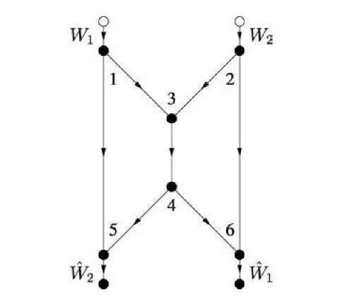
Fig. 4.1 A butterfly network.
Routing
Routing treats communication as path-based flows of bits or packets. Of course, routing does not use coding to combine bits or packets, although one might expand the definition to include copying (see, e.g., [26]). We review routing for the sake of comparing it with network coding in the next section.
Consider the "butterfly" network shown in Figure 4.1, where all edges are non-interfering point-to-point channels with unit capacity. Note that there are no self-loops so that there are no node constraints. Suppose we have two unicast sessions, i.e., two source-sink pairs, as shown in the figure. Clearly, there is exactly one path from node 1 to node 6, namely the sequence of nodes (1,3,4,6) corresponding to a sequence of transmissions on the links (1,3), (3,4), and (4,6). Routing assigns flow (rate) to every path so that no coding (combining of bits, symbols, or packets) is done. A bit received as an input to an intermediate node on a path is merely copied to an output link. One can easily check that routing achieves any rate pair (R1,R2) = (1 — for any 0 < p < 1.
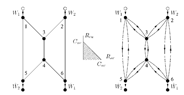
Consider next the undirected network shown on the left in Figure 4.2. The idea is that every edge can be used in either direction as long as the sum of rates (flow) in both directions is at most the capacity of this edge. In other words, every edge is a 2WC that has the capacity region shown in the middle of Figure 4.2.
Fig. 4.2 An undirected butterfly network as a network of 2WCs.
We thus redraw this graph as shown on the right in Figure 4.2. We further model every pair of edges between nodes u and v as Shannon’s push-to-talk 2WC [167, Sec. 1] defined by
where (Zuv ,Zvu) is uniform over![]() for all edges (u,v). The channel (4.1) has the capacity region shown in the middle of Figure 4.2.
for all edges (u,v). The channel (4.1) has the capacity region shown in the middle of Figure 4.2.
Suppose that Cuv = 1 for all edges (u,v). Routing performs better than in Figure 4.1 because there are more paths available from each source to its sink. In fact, there are four paths from node 1 to node 6: path (1,3,4,6), path (1,3,2,6), path (1,5,4,6), and path (1,5,4,3,2,6). We can thus perform routing as shown in Figure 4.3 and achieve the rate pair (R1,R2) = (1,1). This pair defines the capacity region of this network, since the cut-set bound of Section 3.7.1 gives R1 < 1, R2 < 1. In fact, the maximum flow for two unicast sessions on any undirected graph is given by the minimum cut [80]. Note also that one can separate channel coding (PHY layer coding) and routing (network layer coding) to achieve the capacity for this special case. However, such separation of channel and network coding is not always optimal [152].
Fig. 4.3 An optimal routing for the undirected butterfly network.
Network Coding
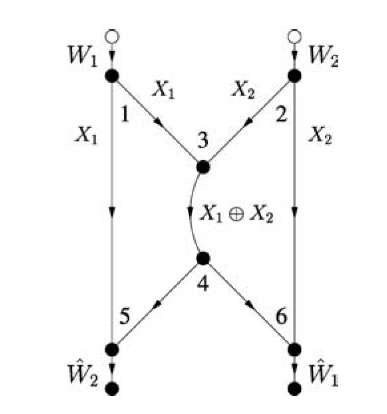
We found that routing achieves a smaller rate region for the directed network of Figure 4.1 than for the undirected network in Figure 4.2. However, suppose that node 3 combines the packets arriving from nodes 1 and 2 by XORing them bit-wise, shown as X1 © X2 in Figure 4.4. This combining of raw bits or packets is called network coding [4]. More specifically, it is called linear network coding if the combining operations are done over a (finite) field [101, 116]. Node 5 collects X1 and X1 © X2 and computes X2. Similarly, node 6 collects X2 and X1 © X2 and computes X1. Thus, network coding achieves the capacity point (R1,R2) = (1,1) even for the directed network of Figure 4.1, and thus outperforms routing by a factor of two in rate. Furthermore, network coding gives an additional method for achieving capacity on the undirected network of Figure 4.2.
Fig. 4.4 Network coding for the directed butterfly network.
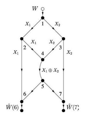
We remark that the rate gains of network coding over routing are the largest for a multicast session, i.e., there is one source and many sinks. For example, the graph in Figure 4.5, which is a simple modification of the graph in Figure 4.1, shows that R = 2 is feasible with network coding while only R = 1 is feasible with routing.
We further remark that the codes in Figures 4.4 and 4.5 were specially chosen by using our knowledge of the network graph. In general, however, the individual nodes must operate without this information (see Table 1.1). An attractive coding method is then to use random network coding [4] or random linear network coding [73]. For the latter approach, consider node u and let Ein(u) and Eout(u) be its sets of incoming and outgoing edges, respectively. Suppose that every packet has L = nb data bits for some integers n and b. Coding at node u proceeds as follows:
(a) for every pair![]() choose a we,/ randomly from the Galois field GF(2b);
choose a we,/ randomly from the Galois field GF(2b);![]()
Fig. 4.5 Network coding for a multicast network.
(b) collect one packet from each incoming edge e and strip off its headers to form the data string xj;
(c) parse xj into n pieces x^(i), i = 1,2,… ,n, having b bits each;
(d) for every outgoing edge f compute
for i = 1,2,… ,n, where the multiplications and additions are over the Galois field GF(2b);
(e) collect the n pieces corresponding to outgoing edge f into ![]()
(f) augment Xj with a header that includes the we,f, e e Ein(u), to inform the decoders of how the packets were combined;
(g) transmit the resulting packet on edge f.
Random linear network coding is known to work well if the size b of the pieces is sufficiently large and if the weights we,f are chosen independently and uniformly over GF(2b). For example, for practical reasons we would like to use b = 1 so that the weights we,f are in GF(2) but then one cannot guarantee that random network coding will work. In this case we must add redundancy, e.g., by using coding at the sources in the form of LT-codes or Raptor codes [128, 168]. The combination of coding at the sources and network coding can provide good rate versus reliability tradeoffs. Many other results on network coding can be found in a recent special issue of the IEEE Transactions on Information Theory devoted in part to this topic [171].
Mode Coding
There are further rate gains possible in wireline networks beyond network coding [105]. To show this, we consider the wireline network in Figure 3.3 with the node constraint (3.1) and Y3 = X2. The graph for this network is shown in Figure 4.6. Suppose for simplicity that the alphabets X1, X2, Y2, Y3 of the respective random variables X1,X2,Y2,Y3 are all the set {0,1}. One might guess that the capacity is 1/2 bit/clock tick because the relay can either receive or transmit, but not both.
Fig. 4.6 A network graph with a relay device constraint.
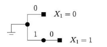
Fig. 4.7 A code tree for the relay in Figure 4.6.
Consider, however, the code tree depicted in Figure 4.7 that is labeled with the symbols X2 that the relay transmits after having decoded an X1 . The idea is that after decoding X1 = 0 the relay sends X2 = 0, while after decoding X1 = 1 the relay uses the channel twice to send the pair of symbols X2,1 = 1 and X2,2 = 0. Note that every codeword in the code tree has exactly one 0, so that the source can transmit exactly one new message bit for every relay codeword. Note further that the tree is labeled so that the code is prefix-free or instantaneously decodable [34, Ch. 5]. This means that the sink can correctly parse its received sequence to extract the message bits.
For example, suppose the message w has 8 bits 0,1,0,0,1,1,1,0. The transmit and receive sequences are then
where x denotes a "do not care" symbol. Note that, for this particular message, we have transmitted 8 bits in n = 13 clock ticks which gives a rate R = 8/13 that is larger than 1/2.
We would like to determine the rate of the above code when the source transmits b bits for large b. The codewords have variable lengths, so we define a random variable L2 to be the length of the codeword of any of the message bits. If the source bits are coin-tossing, we compute
implying that we can substantially increase the rate beyond 1/2 bit/clock tick. In fact, it turns out that better compression codes such as Huffman codes or arithmetic source codes (see [34, Ch. 5]) can achieve R = 0.773 bits/clock tick. Furthermore, this rate is the capacity of the network, as one can check by computing the cut-set bound.
We call the above method mode coding because one is effectively transmitting information through the choice of the relay’s operating mode (listen or talk).1 We will later consider this type of coding in more detail for wireless relays. Note that the relative gains of mode coding are small when the alphabets X1, X2, Y2, Y3 are large. In fact, mode coding boosts the rate by at most 1 bit/packet over an edge time-sharing strategy. But packets often have several thousands of bits. Furthermore, mode coding requires rapid on/off switching by the relay. On the other hand, this coding might be useful for covert communication where, e.g., a router time-jitters transmissions according to a signature pattern.
