Decode-and-Forward
Decode-and-forward is a block-transmission strategy that has the block structure shown in Figure 4.12 [33, 106]. There are two code books: ![]() The source uses block Markov encoding, i.e., the encoding has one block memory in that the source codeword in block b is
The source uses block Markov encoding, i.e., the encoding has one block memory in that the source codeword in block b is ![]() . The idea is that the relay knows wb—1 and decodes wb after having removed the effect of
. The idea is that the relay knows wb—1 and decodes wb after having removed the effect of![]() . The resulting rate bound is
. The resulting rate bound is
The relay can now transmit![]() in block b + 1. The destination decodes wb with a sliding-window decoder that uses
in block b + 1. The destination decodes wb with a sliding-window decoder that uses![]() (cf. [28, 191, 106]). If the codebooks of every block in Figure 4.12 were chosen independently, the resulting destination rate bound is
(cf. [28, 191, 106]). If the codebooks of every block in Figure 4.12 were chosen independently, the resulting destination rate bound is
The term I(X1; Y3 |X2) in (4.31) comes from![]() (note that the destination already knows
(note that the destination already knows![]() and thus
and thus![]() while the term I(X2; Y3) comes from
while the term I(X2; Y3) comes from![]() is treated as interference).
is treated as interference).
Fig. 4.12 A DF strategy for a full-duplex relay.
Fig. 4.13 A DF strategy for a full-duplex relay on an AWGN relay channel.
Summarizing, DF achieves the rate
The reader might wonder why one can optimize over all joint distributions![]() One can permit this by constructing the codebook
One can permit this by constructing the codebook![]() from
from![]() via superposition coding [32]. To explain this method, consider a full-duplex Gaussian relay channel with the DF block structure shown in Figure 4.13. The idea is that the code book
via superposition coding [32]. To explain this method, consider a full-duplex Gaussian relay channel with the DF block structure shown in Figure 4.13. The idea is that the code book![]() is constructed by adding (or superposing) codewords from a Gaussian codebook
is constructed by adding (or superposing) codewords from a Gaussian codebook![]() to codewords from a Gaussian codebook
to codewords from a Gaussian codebook![]() scaled by The codewords in
scaled by The codewords in![]() use power P2. The codewords in
use power P2. The codewords in![]() use power
use power![]() where
where![]() , and the scaled codewords from
, and the scaled codewords from![]() use power
use power![]() i.e., we have
i.e., we have![]() Furthermore, the codeword
Furthermore, the codeword![]() in block b is independent of the codeword
in block b is independent of the codeword![]() , so the source power constraint is satisfied.
, so the source power constraint is satisfied.
The relay decodes wb at the rate![]() The destination decodes wb by using
The destination decodes wb by using![]() and its past estimate of
and its past estimate of ![]() The codeword
The codeword![]() is treated as interference. The resulting
is treated as interference. The resulting
DF rate is
where we recall that![]() is the real part of x, and where
is the real part of x, and where![]()
![]() is the correlation coefficient of the zero-mean X1 and X2, which in this case is
is the correlation coefficient of the zero-mean X1 and X2, which in this case is![]() Note that, by phase-rotating the relay signal appropriately, the source and relay can coherently combine their signals to give the destination an SNR boost. The price paid is a loss in the information rate from the source to the relay.
Note that, by phase-rotating the relay signal appropriately, the source and relay can coherently combine their signals to give the destination an SNR boost. The price paid is a loss in the information rate from the source to the relay.
We make a few remarks. First, DF differs from classic multi-hop in several important ways:
(1) the source and relay transmit simultaneously
(2) the source and relay signals can be made to coherently combine at the destination if h13 and h23 are known to the transmitter or relay
(3) the destination decodes using several or all of its available output blocks.
These differences remain for half-duplex relays. However, the second difference disappears for fast uniform-phase fading or fast Rayleigh fading, as we shall see. Next, note that the last term in (4.32) is the rate of a point-to-point channel where the transmitter has a vector input [X1 X2]. The DF strategy is thus closely related to multi-antenna transmission. In fact, if the source-to-relay channel capacity is large (say, if the relay is close to the source) then the limiting term in (4.32) is I(X1X2; Y3).
Consider again the case P^N = P2/N = 10, Huv = 1 for all (u,v), a = 2, and the linear geometry of Figure 4.8(b). The resulting DF rates are shown in Figure 4.9 as the curve labeled "DF." The curve labeled "p for DF" shows the optimal correlation coefficient. Observe that DF performs well when the relay is close to the source (d w 0) and even meets the cut-set bound (3.33) when d = 0. Based on Figure 4.9, one would choose DF if the relay is close to the source, and CF if the relay is close to the destination. This insight applies to other networks as well. For example, suppose we have two relays. If both relays are close to the source or the destination, then they should both use DF or CF, respectively. On the other hand, if one relay is close to the source and the other is close to the destination, then the former relay should use DF while the latter should use CF.
CF and DF for Fast Uniform-Phase Fading
Consider the geometry of Figure 4.8(a) and where the Huv are fast fading. As noted in Section 4.2.1, we augment Y2 and Y3 to become [Y2 H12] and [Y3 H13 H23], respectively. From (4.23), the CF rate is thus
where
and where![]() For uniform-phase fading, we have
For uniform-phase fading, we have![]()
![]() and choose
and choose![]() is the same as in Section 4.2.4. The result is that we recover the same rate as in (4.28a)-(4.29) (cf. [106]).
is the same as in Section 4.2.4. The result is that we recover the same rate as in (4.28a)-(4.29) (cf. [106]).
On the other hand, the DF rate is now
For the AWGN channel, this rate is
where the expectation is over the![]() that are independent and uniform over
that are independent and uniform over![]() . But Jensen’s inequality gives
. But Jensen’s inequality gives
and we have![]() The best p in (4.37) is therefore zero [79, 106]. This result is intuitive: without phase knowledge the source and relay cannot coherently combine their signals at the destination. The DF block structure thus simplifies to that shown in Figure 4.14.
The best p in (4.37) is therefore zero [79, 106]. This result is intuitive: without phase knowledge the source and relay cannot coherently combine their signals at the destination. The DF block structure thus simplifies to that shown in Figure 4.14.
Fig. 4.14 A DF strategy for a full-duplex relay and p = 0.
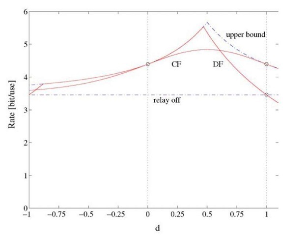
Fig. 4.15 Rates for a full-duplex relay, uniform-phase fading, Pl/N = P2/N = 10, and a = 2.
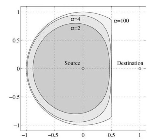
Figure 4.15 plots the CF, DF, and cut-set rates for the linear geometry shown in Figure 4.8(b) and the uniform-phase fading channel with P1/N = P2/N = 10 and a = 2. Perhaps surprisingly, DF achieves capacity when the relay is in a region around the source [106]. Figure 4.16 plots the two-dimensional positions of the relay where DF achieves capacity when P1 = P2. Note that the region grows as a increases. The results in Figures 4.15 and 4.16 generalize to other fast fading channels, e.g., Rayleigh fading channels, and it reinforces the insight from Section 4.2.5 that one should use DF when the relay is near the source. We remind the reader that the distances in
Fig. 4.16 Positions of the relay where DF achieves capacity with uniform-phase fading and Pi = P2.
Figures 4.15 and 4.16 should be interpreted as relative distances and not as absolute ones.
Multipath Decode-and-Forward
Multipath decode-and-forward is a variation of DF where the source node first performs rate-splitting, i.e., the message W with rate R is split into W’ and W” having the respective rates R’ and R" such that R’ + R” = R [33, 44, 106]. The same type of rate-splitting is done for multipath routing in Figure 4.3. In fact, MDF generalizes multipath routing from wireline networks to wireless networks. Alternatively, one could say that MDF combines multipath routing and DF.
The MDF block structure is shown in Figure 4.17. The idea is that one replaces X1 in DF with an auxiliary random variable U, i.e., one performs DF with U playing the role of X1. The U represents codewords ![]() that transmit W’, as shown in Figure 4.17. The "path" for W’ can thus be considered to be the entire RC [65]. On the other hand, W” is transmitted by the codewords
that transmit W’, as shown in Figure 4.17. The "path" for W’ can thus be considered to be the entire RC [65]. On the other hand, W” is transmitted by the codewords![]() that are superposed on
that are superposed on![]() The "path" for W” can thus be considered to be the direct link from the source to the relay.
The "path" for W” can thus be considered to be the direct link from the source to the relay.
Fig. 4.17 An MDF strategy for a full-duplex relay.
Suppose the destination first decodes the messages w[ and then the wf. Based on the above discussion, the rate of MDF is a sum of a DF rate and a point-to-point rate:
The MDF superposition method is shown for AWGN channels in Figure 4.18 that generalizes Figure 4.13. The codebook![]() is constructed by adding codewords from the Gaussian codebooks
is constructed by adding codewords from the Gaussian codebooks![]()
![]() The codewords in
The codewords in![]() use power P2. The code words in
use power P2. The code words in![]() have powers
have powers![]() respectively, where
respectively, where
![]() We must therefore choose
We must therefore choose![]() The decoding procedure is as follows. The relay decodes
The decoding procedure is as follows. The relay decodes![]() after receiving
after receiving![]() The destination decodes
The destination decodes![]() after receiving
after receiving![]() ~ by assuming that its past estimate of
~ by assuming that its past estimate of![]() is correct, and by treating
is correct, and by treating ![]() as interference. Finally, the destination removes the effect of
as interference. Finally, the destination removes the effect of![]() and decodes
and decodes![]()
Fig. 4.18 An MDF strategy for a full-duplex relay on an AWGN relay channel.
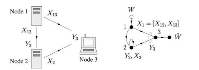
Fig. 4.19 A mixed wireline/wireless relay channel and its graph.
Unfortunately, for full-duplex AWGN channels the MDF method does not improve the DF method because the optimal choice of PUXiX2 gives either DF or a point-to-point strategy. However, for other AWGN channels the MDF strategy performs better than DF. For example, we shall later see that MDF improves on DF for half-duplex channels. MDF even achieves capacity for an important class of channels discussed next.
Suppose we have the mixed network shown in Figure 4.19 where the source-to-relay channel is a wireline channel. We model this by using X1 = [X12 X13] and the channel
where we permit X2 to contribute to Y2, i.e., the channel (4.41) includes port constraints such as (3.1). For the MDF rate (4.40), we choose U = X12 and
We compute
where the maximization is over all distributions of the form (4.42). One can check that the cut-set bound (3.33) also gives (4.43) because the best input distributions factor as (4.42). The MDF rate (4.43) is therefore the capacity of the mixed relay channel [47].
We remark that this channel also models cases where nodes 1 and 2 are wireless and the source-to-relay channel is "orthogonal" to the destination channel. For example, this happens if the source-to-relay channel uses a different frequency band than the destination channel.


![tmp8-222_thumb[2] tmp8-222_thumb[2]](http://what-when-how.com/wp-content/uploads/2011/07/tmp8222_thumb2_thumb.jpg)
![tmp8-261_thumb[2] tmp8-261_thumb[2]](http://what-when-how.com/wp-content/uploads/2011/07/tmp8261_thumb2_thumb.jpg)
![tmp8-270_thumb[2] tmp8-270_thumb[2]](http://what-when-how.com/wp-content/uploads/2011/07/tmp8270_thumb2_thumb.png)
![tmp8-271_thumb[2] tmp8-271_thumb[2]](http://what-when-how.com/wp-content/uploads/2011/07/tmp8271_thumb2_thumb.png)
![tmp8-280_thumb[2] tmp8-280_thumb[2]](http://what-when-how.com/wp-content/uploads/2011/07/tmp8280_thumb2_thumb.png)
![tmp8-281_thumb[2] tmp8-281_thumb[2]](http://what-when-how.com/wp-content/uploads/2011/07/tmp8281_thumb2_thumb.png)
![tmp8-286_thumb[2] tmp8-286_thumb[2]](http://what-when-how.com/wp-content/uploads/2011/07/tmp8286_thumb2_thumb.png)


![tmp8-300_thumb[2] tmp8-300_thumb[2]](http://what-when-how.com/wp-content/uploads/2011/07/tmp8300_thumb2_thumb.jpg)


![tmp8-336_thumb[2] tmp8-336_thumb[2]](http://what-when-how.com/wp-content/uploads/2011/07/tmp8336_thumb2_thumb.jpg)
