The previous sections describe device (node) and channel (edge) models. A communication network also has sources and sinks, and we will consider bit sources where every bit is uniformly distributed and is independent of all other message bits. We thereby implicitly assume that multimedia signals, such as voice or video, are compressed to bit streams, and any intra- or inter-source correlations are ignored. In other words, we assume there is a separation (layering) between the application layer and the rest of the network protocol stack. This topic further assumes that the sources are not bursty, i.e., any source time variations are smoothed by large buffers, and delay is not critical.
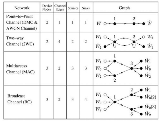
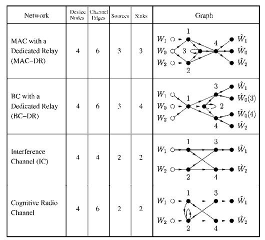
It remains to specify where sources and sinks are located. Once this choice is made, one has a network that is often referred to as a "channel" in the information theory literature. For example, Figures 3.7-3.9 show several such "channels." In these figures, the source emits a message Wm (represented by a hollow node) and a sink accepts an estimate Wm (represented by a solid node) of Wm. If Wm is decoded at more than one node, we write Wm(u) to represent an estimate of Wm at node u. We begin by discussing some basic networks.
Fig. 3.7 Basic networks.
Fig. 3.8 Cooperative networks with three device nodes.
Fig. 3.9 Networks with four device nodes.
(1) A point-to-point channel (see Section 2.2.1) has two device nodes, one channel edge, one source, and one sink (see Figure 3.7). Device node 1 has a channel input X and device node 2 has a channel output Y. The channel is often modeled as being memoryless in the sense that an output Yi at time i is affected only by the input Xi at time i, i.e., Yi is statistically independent of all other inputs and outputs given Xi. One can therefore define a noisy channel by a single-sample (or "single-letter") conditional probability distribution PY|X. If the alphabets X and Y of the respective X and Y are discrete and finite, the channel is called a discrete memoryless channel or DMC [34, p. 193], [35, p. 100], [56, p. 73] (see Section 2.2.1). If the channel is noise-free, as in Figure 3.1, then we have
where 1(-) is the indicator function that is 1 if its argument is true and is 0 otherwise. If the alphabets are continuous, e.g., for AWGN channels such as (3.3a), then one focuses on a conditional probability density pY|X(■). Alternatively, one simply considers a sum as in (3.3a).
(2) A two-way channel (2WC) has two sources and sinks [167]. Device node u, u = 1,2, has one channel input Xu and one channel output IV The self-loops in Figure 3.7 specify that Xu contributes to Yu for both u. This would occur, e.g., if the graph represents a wireless network where both nodes have the half-duplex constraint (3.7). The channel is often modeled as being memoryless in the sense that an output Yu,i at time i is affected only by the inputs X1,i and X2,i at time i, and is statistically independent of all other past inputs and outputs (note that Yu>i generally contributes to future Xu,k, k > i; Yu>i can thus be statistically dependent on future Xu,&). One can define the memoryless channel by a conditional probability distribution PYlY2|XlX2. Note that a 2WC includes a DMC as a special case, both without or with feedback from node 2 to node 1.
(3) A multiaccess channel (MAC) has three device nodes, three sources and sinks, and all sinks are located at device node 3 [2, 119], [35, p. 270], [34, p. 388]. Note that the common message Wo is given to both nodes 1 and 2. The memory-less MAC is defined by a conditional probability distribution PY3|XlX2. For simplicity, one often ignores the subscript 3 and replaces Y3 by Y.
(4) A broadcast channel (BC) has three device nodes, three sources, and four sinks, and all sources are located at node 1 [35, p. 359], [34, p. 418]. The common message W0 is decoded at both receive nodes 2 and 3. The memoryless BC is defined by a conditional probability distribution PY2Y3|Xl. Again, for simplicity one often writes X in place of X1 , and Y1, Y2 in place of Y2, Y3.
For the networks in Figure 3.7, only the 2WC has nodes that actively cooperate; the other networks have nodes that cooperate only in the sense that they can, say, agree on a common time reference. Figure 3.8 shows some cooperative networks with three nodes.
(1) A relay channel (RC) has one source and sink [33], [34, p. 428], [180], [181]. More generally, a RC has many device nodes, but only one source and sink. The device nodes without sources and sinks are called relays and aid communication, perhaps generously, or through incentives, or competitively. Observe that the relay in Figure 3.8 has a self-loop, which is needed if there is a half-duplex constraint (3.7) for example. The graph in Figure 3.5 thus permits full-duplex transmission since X2 does not affect Y2. A memoryless RC can be defined by PY2y3|XlX2. Note that, even if the RC is memoryless, the network does have memory in the sense that there is a processing delay at the relay.
(2) A MAC with generalized feedback (MAC-GF) has three sources and sinks like a MAC, but now the source device nodes can cooperate [28], [99], [187]. The MAC-GF includes the RC as a special case by setting Wo and W2 to be constants and by letting node 1 transmit but not receive. In this case, node 2 transmits only as a relay for node 1. A memoryless MAC-GF can be defined by PYlY2Y3|XlX2.
(3) A three-way channel (3WC) is the most general network with three device nodes. The 3WC has 9 sources and 12 sinks: there is a common message and two "private" messages at each node. The 3WC includes all of the previous networks as special cases (DMC, 2WC, MAC, BC, RC, MAC-GF). The memoryless 3WC channel is defined by PYlY2Y3|XiX2X3 (•).
The last set of networks we consider have four device nodes, as shown in Figure 3.9. These networks will serve as examples describing communication strategies later on.
(1) A multi-access relay channel (MARC) or MAC with a dedicated relay (MAC-DR) is a MAC with one extra device node that acts as a relay [110, 156]. For example, such a situation might occur in a wireless cellular network where a relay station (node 3) helps to transmit data to a base station (node 4). A memoryless MAC-DR can be defined by PY3 Y41 Xi X2 X3 (‘).
(2) A BC with a dedicated relay (BC-DR) is a BC with an extra relay node [106, 118]. A memoryless BC-DR can be defined by PY2Y3Y4|XlX2 (,).
(3) An interference channel (IC) is a non-cooperative model where two device nodes interfere with each other’s transmissions [3, 68]. A memoryless IC can be defined by PY3Y4|XlX2 (•).
(4) Alternatively, suppose node 2 attempts to cooperate. One might add a directed edge from node 1 to node 2, say, as well as a self-loop at node 2 to include a half-duplex constraint. This channel has been dubbed a cognitive radio channel because of its relation to cognitive radio applications [40].


