We outline a code construction for half-duplex relays and for the Rayleigh fading channels of Section 4.4. The design is based on a point-to-point multi-antenna strategy known as Diagonal Bell Labs Layered Space-Time (D-BLAST) [53]. Other code constructions for relay channels are described in, e.g., [83, 200] (convolutional codes), [111] (space-time codes), [198] (turbo codes), [97, 104, 153, 50] (low-density parity-check (LDPC) codes).
We use two different codes: one for each of the two messages in the first two blocks in Figure 4.24. The relay must decode w1 after having received only the first block of outputs from the source. We therefore require Rc < 1/2 for the w1 encoder since half of the symbols will be erased (we assume the even- and odd-numbered blocks in Figure 4.24 have the same length; we further assume the source and relay use the same signal/modulation set). We remark that MDF for half-duplex relaying does not suffer from error propagation, in contrast to MDF for full-duplex relaying and D-BLAST for point-to-point channels.
Code design is usually done by using density evolution [154] or EXIT charts [175]. We use the latter approach and design irregular low-density parity-check (LDPC) codes with the curve-fitting procedure described in [176]. The coded bits are mapped to QPSK symbols via the Gray mapping. The decoder uses the standard graph representation of an LDPC code with variable nodes on the left and check nodes on the right. The left and right nodes are connected by edges whose nodes are chosen with a random permutation that avoids 2-cycles. The decoder iterates 60 times between the left and right nodes by using an a posteriori probability (APP) decoder.
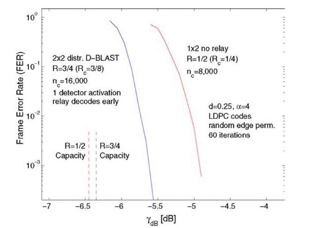
Consider the 1 x 1 x 2 setup of Figure 4.26 and d = 0.25. Consider R = 1/2 without a relay. We design an LDPC code with rate Rc = 1/4 and length nc = 8000 that has an (single-antenna, no fading, BPSK) AWGN decoding threshold of (Eb/N0)dB = —0.4 dB which is about 0.3 dB from capacity. The resulting frame error rates (FER) are shown on the right in Figure 4.27. Observe that the code operates within 1.5 dB of capacity at an FER of 10-3. The extra loss (as compared to 0.3 dB for the single-antenna case) can be attributed to the short code length and the fading.
Consider next R = 1. We design an LDPC code with rate Rc = 3/8 and length nc = 16,000 that has an (single-antenna, no fading, BPSK) AWGN decoding threshold of (Eb/N0)dB = 0.1 dB which is about 0.45 dB from capacity. The encoding and decoding procedure is as follows (see Figure 4.24).
• In the odd-numbered blocks b = 1,3,5,…, the source transmits 4000 QPSK symbols (or 8000 of the 16,000 codeword bits) by using the rate Rc = 3/8 LDPC code.
• After every odd-numbered block b, the relay decodes the information bits of the Rc = 3/8 code from this block. Note that the relay has received only half of this codeword’s symbols.
Fig. 4.27 MDF frame error rates for the 1 X 1 X 2 scenario.
• In the even-numbered blocks b = 2,4,6,…, the source transmits using the rate Rc = 1/4 code described above.
• In the even-numbered blocks, the relay encodes the information bits decoded from the previous block by using the Rc = 3/8 encoder and transmits the last 4000 QPSK symbols of this codeword (or the last 8000 of the 16,000 codeword bits).
• After every even-numbered block, the sink decodes the information bits of the rate Rc = 3/8 code. The sink performs only one detector activation per codeword (we remark that multiple detector activations would improve the performance a little [176]).
• The sink cancels the interference caused by the symbols of the Rc = 3/8 code from the even-numbered blocks.
• After every even-numbered block, the sink decodes the information bits of the Rc = 1/4 code.
The overall rate is R = 2(3/8) +2(1/4)(1/2) = 1 bit per use, where the leading factors 2 are due to the QPSK modulation. There are three decoding steps to consider.
• The FER of the relay decoding step is not shown in Figure 4.27 because it lies far to the left of the other two curves.
• The FER of the sink decoding the information bits from the Rc = 3/8 code is shown as the left curve in Figure 4.27 (labeled "2 x 2 distr. D-BLAST").
• The FER of the sink decoding the information bits from the Rc = 1/4 code is the same as the case where there is no relay, and is the curve on the right in Figure 4.27.
We see that the dominating FER is in both cases (without and with a relay) due to the direct link from the source to the sink. The reliability of the two schemes is therefore the same. However, the MDF scheme doubles the rate.

