Vanishing Points
If there is no clipping, then after one has the camera coordinates of a point, the next problem is to project to the view plane z = d. The central projection p of R3 from the origin to this plane is easy to compute. Using similarity of triangles, we get
Let us see what happens when lines are projected to the view plane. Consider a line through a point![]() with direction vector
with direction vector![]() and
and
This line is projected by![]() to a curve
to a curve![tmpc646506_thumb[2] tmpc646506_thumb[2]](http://what-when-how.com/wp-content/uploads/2012/06/tmpc646506_thumb2_thumb.png) in the view plane, where
in the view plane, where
It is easy to check that the slope of the line segment from is
which is independent of t1 and t2. This shows that the curve p’(t) has constant slope and reconfirms the fact that central projections project lines into lines (but not necessarily onto).
Next, let us see what happens to p’(t) as t goes to infinity. Assume that![]() Then, using equation (4.7), we get that
Then, using equation (4.7), we get that
This limit point depends only on the direction vector v of the original line. What this means is that all lines with the same direction vector, that is, all lines parallel to the original line, will project to lines that intersect in a point. If c = 0, then one can check that nothing special happens and parallel lines project into parallel lines.
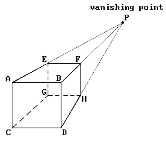
Figure 4.5. Vanishing point.
In the context of the world-to-view plane transformation with respect to a given camera, what we have shown is that lines in the world project into lines in the view plane. Furthermore, the projection of some lines gives rise to certain special points in the view plane. Specifically, let L be a line in the world and let equation (4.6) be a parameterization for L in camera coordinates. We use the notation in the discussion above.
Definition. If the point in the view plane of the camera that corresponds to the point on the right hand side of equation (4.8) exists, then it is called the vanishing point for the line L with respect to the given camera or view.
Clearly, if a line has a vanishing point, then this point is well-defined and unique. Any line parallel to such a line will have the same vanishing point. Figure 4.5 shows a projected cube and its vertices. Notice how the lines through the pairs of vertices A and E, B and F, C and G, and D and H meet in the vanishing point P. If we assume that the view direction of the camera is perpendicular to the front face of the cube, then the lines through vertices such as A, B, and E, F, or A, C, and B, D, are parallel. (This is the c = 0 case.)
Perspective views are divided into three types depending on the number of vanishing points of the standard unit cube (meaning the number of vanishing points of lines parallel to the edges of the cube).
One-point Perspective View. Here we have one vanishing point, which means that the view plane must be parallel to a face of the cube. Figure 4.5 shows such a perspective view.
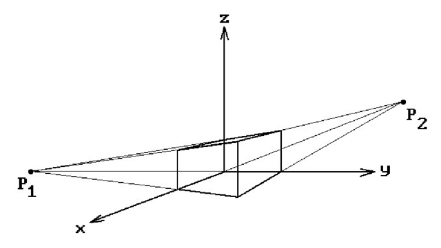
Two-point Perspective View. Here we have two vanishing points and is the case where the view plane is parallel to an edge of the cube but not to a face. See Figure 4.6 and the vanishing points P1 and P2.
Figure 4.6. Two-point perspective view.
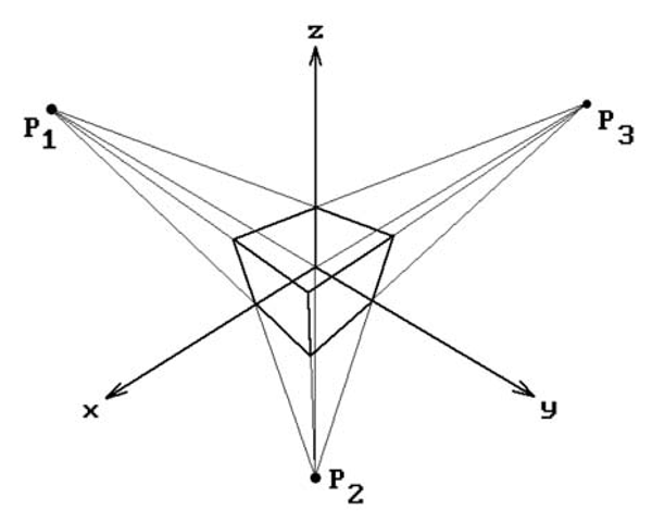
Figure 4.7. Three-point perspective view.
Three-point Perspective View. Here we have three vanishing points and is the case where none of the edges of the cube are parallel to the view plane. See Figure 4.7 and the vanishing points![tmpc646519_thumb[2] tmpc646519_thumb[2]](http://what-when-how.com/wp-content/uploads/2012/06/tmpc646519_thumb2_thumb.png)
Two-point perspective views are the ones most commonly used in mechanical drawings. They show the three dimensionality of an object best. Three-point perspective views do not add much.
Windows and Viewports Revisited
Assume that [wxmin,wxmax] x [wymin,wymax] and [vxmin,vxmax] x [vymin,vymax] define the window and viewport rectangles, respectively. See Figure 4.8. We shall not change the basic idea that a window specifies what we see and that the viewport specifies where we see it, but there was a natural implication that it is by changing the window that one sees different parts of the world. Is that not how one would scan a plane by moving a rectangular window around in it?
Figure 4.8. The window and viewport rectangles.
What is overlooked here is the problem that occurs when the viewport and the window are not the same size rectangle. For example, suppose that the window is the square [-2,2] x [-2,2] and that the viewport the rectangle [0,100] x [0,50]. What would happen in this situation is that the circle of radius 1 around the origin in the view plane would map to an ellipse centered at (50,25) in the viewport. What we know to be a circle in the world would show up visually as an ellipse on the screen. Would we be happy with that? This is the “aspect ratio” problem. The reader may have noticed this already when implementing some of the programming projects. What can one do to make circles show up as circles?
The best way to deal with the aspect ratio problem would be to let the user change the viewport but not the window. The window would then be chosen to match the viewport appropriately. First of all, users are not interested in such low level concepts anyway and want to manipulate views in more geometric ways by using commands like “pan,” “zoom,” “move the camera,” etc. Secondly, in the case of 3d graphics, from a practical point of view this will in no way affect the program’s ability to handle different views. Changing the camera data will have the same effect. In fact, changing the position and direction of the camera gives the program more control of what one sees than simply changing the window. Changing the distance that the view plane is in front of the camera corresponds to zooming. A fixed window would not work in the case of 2d graphics, however. One would have to let the user translate the window and change its size to allow zooming. A translation causes no problem, but the zooming has to be controlled. The size can only be allowed to change by a factor that preserves the height divided by width ratio. There is no reason for a user to know what is going on at this level though. As long as the user is given a command option to zoom in or out, that user will be satisfied and does not need to know any of the underlying technical details.
Returning to the 3d graphics case, given that our default window will be a fixed size, what should this size be? First of all, it will be centered about the origin of the view plane. It should have the same aspect ratio (ratio of height to width) as the viewport. Therefore, we shall let the window be the rectangle [-1,1] x [-b,b], where b = (vymax – vymin)/(vxmax – vxmin). Unfortunately, this is not the end of the story. There is also a hardware aspect ratio one needs to worry about. This refers to the fact that the dots of the electron beam for the CRT may not be “square.”
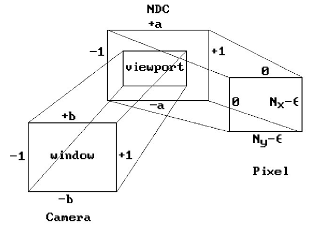
Figure 4.9. Window, normalized viewport, and pixel space.
The hardware ratio is usually expressed in the form a = ya/xa with the operating system supplying the values xa and ya. In Microsoft Windows, one gets these values via the calls
where hdc is a “device context” and ASPECTX and ASPECTY are system-defined constants.
To take the aspect ratios into account and to allow more generality in the definition of the viewport, Blinn ([Blin92]) suggests using normalized device coordinates (NDC) for the viewport that are separate from pixel coordinates. The normalized viewport in this case will be the rectangle [-1,1] x [-a,a], where a is the hardware aspect ratio. If Nx and Ny are the number of pixels in the x- and y-direction of our picture in pixel space, then Figure 4.8 becomes Figure 4.9.
We need to explain the “-e” terms in Figure 4.9. One’s first reaction might be that [0,Nx - 1] x [0,Ny - 1] should be the pixel rectangle. But one needs to remember our discussion of pixel coordinates in Section 2.8. Pixels should be centered at half integers, so that the correct rectangle is [-0.5,Nx - 0.5] x [-0.5,Ny - 0.5]. Next, the map from NDC to pixel space must round the result to the nearest integer. Since rounding is the same thing as adding 0.5 and truncating, we can get the same result by mapping [-1,1] x [-a,a] to [0,Nx] x [0,Ny] and truncating. One last problem is that a +1 in the x- or y-coordinate of a point in NDC will now map to a pixel with Nx or Ny in the corresponding coordinate. This is unfortunately outside our pixel rectangle. Rather than looking for this special case in our computation, the quickest (and satisfactory) solution is to shrink NDC slightly by subtracting a small amount e from the pixel ranges. Smith suggests letting e be 0.001.
There is still more to the window and viewport story, but first we need to talk about clipping.
The Clip Coordinate System
Once one has transformed objects into camera coordinates, our next problem is to clip points in the camera coordinate system to the truncated pyramid defined by the near and far clipping planes and the window. One could do this directly, but we prefer to transform into a coordinate system, called the clip coordinate system or clip space, where the clipping volume is the unit cube [0,1] x [0,1] x [0,1]. We denote the transformation that does this by![tmpc646524_thumb[2] tmpc646524_thumb[2]](http://what-when-how.com/wp-content/uploads/2012/06/tmpc646524_thumb2_thumb.png) There are two reasons for using this transformation:
There are two reasons for using this transformation:
(1) It is clearly simpler to clip against the unit cube.
(2) The clipping algorithm becomes independent of boundary dimensions.
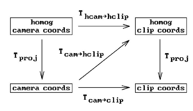
Actually, rather than using these coordinates we shall use the associated homogeneous coordinates. The latter define what we shall call the homogeneous clip coordinate system or homogeneous clip space. Using homogeneous coordinates will enable us to describe maps via matrices and we will also not have to worry about any divisions by zero on our way to the clip stage. The map![tmpc646525_thumb[2] tmpc646525_thumb[2]](http://what-when-how.com/wp-content/uploads/2012/06/tmpc646525_thumb2_thumb.png) in Figure 4.1 refers to this camera-to-homogeneous-clip coordinates transformation. Let
in Figure 4.1 refers to this camera-to-homogeneous-clip coordinates transformation. Let![]() denote the corresponding homogeneous-camera-to-homogeneous-clip coordinates transformation. Figure 4.10 shows the relationships between all these maps. The map Tproj is the standard projection from homogeneous to Euclidean coordinates.
denote the corresponding homogeneous-camera-to-homogeneous-clip coordinates transformation. Figure 4.10 shows the relationships between all these maps. The map Tproj is the standard projection from homogeneous to Euclidean coordinates.
Assume that the view plane and near and far clipping planes are a distance d, dn, and df in front of the camera, respectively. To describe![tmpc646527_thumb[2] tmpc646527_thumb[2]](http://what-when-how.com/wp-content/uploads/2012/06/tmpc646527_thumb2_thumb.png) it will suffice to describe
it will suffice to describe![]()
First of all, translate the camera to (0,0,-d). This translation is represented by the homogeneous matrix
Figure 4.10. The camera-to-clip space transformations.
Next, apply the projective transformation with homogeneous matrix![tmpc646536_thumb[2] tmpc646536_thumb[2]](http://what-when-how.com/wp-content/uploads/2012/06/tmpc646536_thumb2_thumb.png) where
where
To see exactly what the map defined by![tmpc646539_thumb[2] tmpc646539_thumb[2]](http://what-when-how.com/wp-content/uploads/2012/06/tmpc646539_thumb2_thumb.png) does geometrically, consider the lines
does geometrically, consider the lines
In particular,
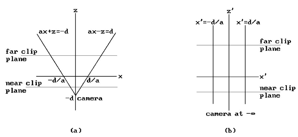
This shows that the camera at (0,0,-d) has been mapped to “infinity” and the two lines have been mapped to the lines![]() respectively, in the plane y = 0.
respectively, in the plane y = 0.
See Figure 4.11. In general, lines through (0,0,-d) are mapped to vertical lines through their intersection with the x-y plane. Furthermore, what was the central projection from the point (0,0,-d) is now an orthogonal projection of R3 onto the x-y plane. It follows that the composition of![]() maps the camera off to “infinity,” the near clipping plane to
maps the camera off to “infinity,” the near clipping plane to![]() and the far clipping plane to
and the far clipping plane to![]() .
.
The perspective projection problem has been transformed into a simple orthographic projection problem (we simply project (x,y,z) to (x,y,0)) with the clip volume now being
Figure 4.11. Mapping the camera to infinity.
To get this new clip volume into the unit cube, we use the composite of the following maps: first, translate to
and then use the radial transformation which multiplies the x, y, and z-coordinates by
respectively. If![tmpc646560_thumb[2] tmpc646560_thumb[2]](http://what-when-how.com/wp-content/uploads/2012/06/tmpc646560_thumb2_thumb.png) is the homogeneous matrix for the composite of these two maps, then
is the homogeneous matrix for the composite of these two maps, then
so that
is the matrix for the map![tmpc646564_thumb[2] tmpc646564_thumb[2]](http://what-when-how.com/wp-content/uploads/2012/06/tmpc646564_thumb2_thumb.png) that we are after. It defines the transformation from homogeneous camera to homogeneous clip coordinates. By construction the map
that we are after. It defines the transformation from homogeneous camera to homogeneous clip coordinates. By construction the map![]() sends the truncated view volume in camera coordinates into the unit cube
sends the truncated view volume in camera coordinates into the unit cube![]() in clip space.
in clip space.
Note that the camera-to-clip-space transformation does not cost us anything because it is computed only once and right away combined with the world-to-camera-space transformation so that points are only transformed once, not twice.
Finally, our camera-to-clip-space transformation maps three-dimensional points to three-dimensional points. In some cases, such as for wireframe displays, the z-coordinate is not needed and we could eliminate a few computations above. However,if we want to implement visible surface algorithms, then we need the z. Note that the transformation is not a motion and will deform objects. However, and this is the important fact, it preserves relative z-distances from the camera and to determine the visible surfaces we only care about relative and not absolute distances. More precisely, let p1 and p2 be two points that lie along a ray in front of the camera and assume that they map to p1/ and p2′, respectively, in clip space. If the z-coordinate of p1 is less than the z-coordinate of p2, then the z-coordinate of p1/ will be less than the z-coordinate of p2′. In other words, the “in front of” relation is preserved. To see this, let![]() It follows from (4.10) that
It follows from (4.10) that
![tmpc646509_thumb[2] tmpc646509_thumb[2]](http://what-when-how.com/wp-content/uploads/2012/06/tmpc646509_thumb2_thumb.png)
![tmpc646512_thumb[2] tmpc646512_thumb[2]](http://what-when-how.com/wp-content/uploads/2012/06/tmpc646512_thumb2_thumb.png)

![tmpc646523_thumb[2] tmpc646523_thumb[2]](http://what-when-how.com/wp-content/uploads/2012/06/tmpc646523_thumb2_thumb.png)
![tmpc646534_thumb[2] tmpc646534_thumb[2]](http://what-when-how.com/wp-content/uploads/2012/06/tmpc646534_thumb2_thumb.png)
![tmpc646538_thumb[2] tmpc646538_thumb[2]](http://what-when-how.com/wp-content/uploads/2012/06/tmpc646538_thumb2_thumb.png)
![tmpc646547_thumb[2] tmpc646547_thumb[2]](http://what-when-how.com/wp-content/uploads/2012/06/tmpc646547_thumb2_thumb.png)
![tmpc646556_thumb[2] tmpc646556_thumb[2]](http://what-when-how.com/wp-content/uploads/2012/06/tmpc646556_thumb2_thumb.png)
![tmpc646558_thumb[2] tmpc646558_thumb[2]](http://what-when-how.com/wp-content/uploads/2012/06/tmpc646558_thumb2_thumb.png)
![tmpc646559_thumb[2] tmpc646559_thumb[2]](http://what-when-how.com/wp-content/uploads/2012/06/tmpc646559_thumb2_thumb.png)
![tmpc646562_thumb[2] tmpc646562_thumb[2]](http://what-when-how.com/wp-content/uploads/2012/06/tmpc646562_thumb2_thumb.png)
![tmpc646563_thumb[2] tmpc646563_thumb[2]](http://what-when-how.com/wp-content/uploads/2012/06/tmpc646563_thumb2_thumb.png)
![tmpc646572_thumb[2] tmpc646572_thumb[2]](http://what-when-how.com/wp-content/uploads/2012/06/tmpc646572_thumb2_thumb.png)
![tmpc646573_thumb[2] tmpc646573_thumb[2]](http://what-when-how.com/wp-content/uploads/2012/06/tmpc646573_thumb2_thumb.png)
