Drawing Ellipses and Other Conics
The equation for the standard ellipse centered at the origin is
and we can generate points on it using the standard parameterization
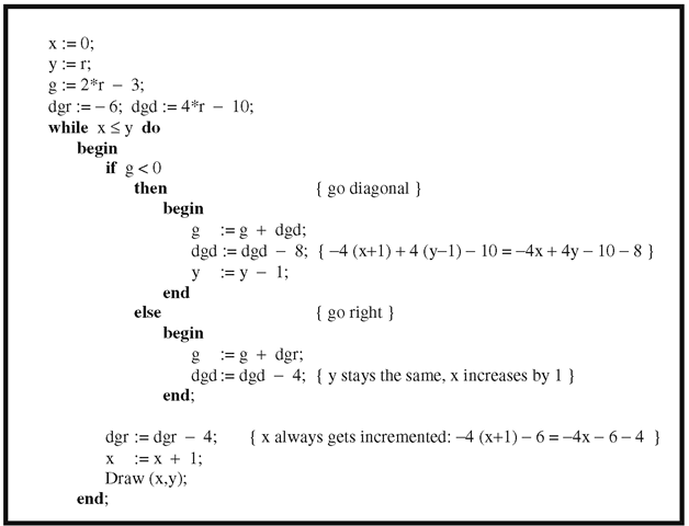
Algorithm 2.9.2.2. An improved Bresenham circle-drawing algorithm (one octant).
Differentiating equation (2.6) implicitly gives the differential equation
This leads to a DDA approach similar to the case of a circle.
Because ellipses are an important class of curves, many algorithms exist to draw them. The Bresenham approach to drawing a circle can be extended to ellipses, but that algorithm will no longer guarantee a minimum linear error between the ellipse and the chosen pixels. See [Mcil92] for a correct Bresenham-type algorithm. Alternatively, a version of the midpoint algorithm described in Section 2.5.3 produces an efficient and more accurate algorithm. For more details and other references see [VanN85] and [Roge98].
Special algorithms for generating parabolas and hyperbolas are also known. We shall not describe any here but instead jump directly to the case of a general conic. Every conic can be defined implicitly by an equation of the form
Given a starting pixel on the conic, one can determine which adjacent pixel to pick next similar to what we did in the case of circles by looking at an error function. Each possible move will have an error associated to it and we simply choose the move with the least error. It is easy to show that the error functions have the same form as the equation of the conic and that they can be computed incrementally. See [Blin88a] and [Chan88] for more details.
Conics are a special case of implicitly defined curves and general algorithms for generating such curves will be presented in Section 14.5.1.
Bit Map Graphics
There are lots of situations in graphics where one needs to map blocks of bits from one location to another. Today’s graphical user interfaces present a user with many “windows” that pop on and off the screen. Animation techniques usually achieve their motion effect by mapping a saved block of pixels to the current location of the moving figure (thereby erasing it and restoring the background) and then mapping another block containing the figure to its new location. This section looks at some rectangular bit map basics. The discussion is specific for the IBM PC, although most of it is generic. For a more extensive discussion see [Miel91], [FVFH90], and [DeFL87].
First of all, what does it take to define a bit map? Rectangles are specified by the upper left and lower right corner:
A bit map specifies a rectangle in a possibly larger rectangle:
Bit maps are stored in row major form in memory. The width field refers to a possible larger bitmap that contains this rectangle. For example, the rectangle may be properly contained in a frame buffer whose pixels are stored in row major form. In that case, the pixels of the rectangle do not form a contiguous sequence and one needs the width of the bigger frame buffer to be able to access the pixels of the rectangle as one moves from one row to the next. See Figure 2.20. Note that each row of a rectangle is assumed to specify a contiguous chunk of bits in memory however.
Figure 2.20. Specifying bit maps.
Several modes are allowed in bit map copying:
One often allows a “texture” so that one can generate patterns.
The value of texlen depends on the graphics hardware. Each bit in the texture array indicates whether the corresponding bit in the source rectangle is to be copied.
Here are the basic parameters of a bitBlt (bit block transfer) procedure:
Sometimes the source rectangle is specified instead of the target rectangle. In any case, both the source and target rectangle are the same size and may need to be clipped against their associated bit maps. The bit maps themselves may overlap so that the copy operation must be careful not to overwrite essential data. Here is an outline for the procedure:
texture = byte array [1..texlen];
Before each bit is copied, one checks the appropriate bit in the texture array. A “1” means that the bit is to be copied, a “0,” that it is not. If a source bit sB is to be copied, then the target bit tB is replaced by sB op tB using the current copying mode op.
Although the abstract code for a bitBlt operation is straightforward, the tricky part is to implement it as efficiently as possible. For that reason, such operations are usually implemented in assembly language. A complicating factor is when addresses do not fall on word boundaries. Efficient coding is absolutely essential here and can speed up the speed of the procedure by orders of magnitude!
An important application of BitBlt procedures is managing a cursor on the screen. What this involves is mapping predefined bit maps to specified locations on the screen. A cursor corresponds to a small rectangle of bits. In Section 1.3 we already described a simple way to move a cursor is using xor mode along with the advantages and disadvantages of this method.
2D Animation
The object of this section is to describe a few simple aspects of two-dimensional animation. The general topic is much too large to do more than that here, especially since much of it is not really a topic in geometric modeling per se. On the other hand, many of the techniques used in two-dimensional computer animation belong in a discussion of raster graphics. This is certainly true of that part of animation which deals with showing moving objects and which lends itself to a lot of fun programming exercises. Keep in mind though that animation techniques have changed along with hardware. All we shall basically do here is describe a few interesting tricks that deal with Boolean operations on bits. These tricks were especially important in the early days of graphics where one had only a single frame buffer and not the multiple buffers that one finds in graphics systems today. We shall have a little to say about animation of three-dimensional objects in Sections 4.13 and 4.14.
Showing moving objects is accomplished by showing a sequence of still objects, where each individual picture shows the objects moved slightly from their previous position. Here are some simple methods by which one can perform such animation, starting with the most basic:
(1) Redraw the whole screen for each new image.
(2) If the objects consist of lines, then simply erase the current lines and redraw them at the new location.
(3) Erase/draw objects using block write commands.
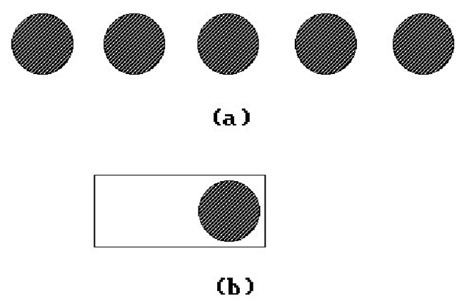
(4) Use an approach similar to (3), except let each block have “trailing” blanks, so that each new block write erases and draws simultaneously. This reduces the number of block writes. An example of this is shown in Figure 2.21. If we wanted to show a ball moving from left to right, we could show the ball at the sequence of locations shown in (a). Rather than writing blocks of pixels the size of the ball, we could write a block shown in (b) which simultaneously erases the previous ball as it writes the new one.
(5) Use bit operations such as xor, and, or more general BitBlt procedures. We have already discussed in Section 1.3 how xor mode is useful in moving a cursor without disturbing the background. One can also use xor to do “rubber banding.” For example, to drag a line anchored to a point around on the screen with the mouse, one would perform the following two instructions in a loop:
Figure 2.21. Animating with "trailing blank" blocks.
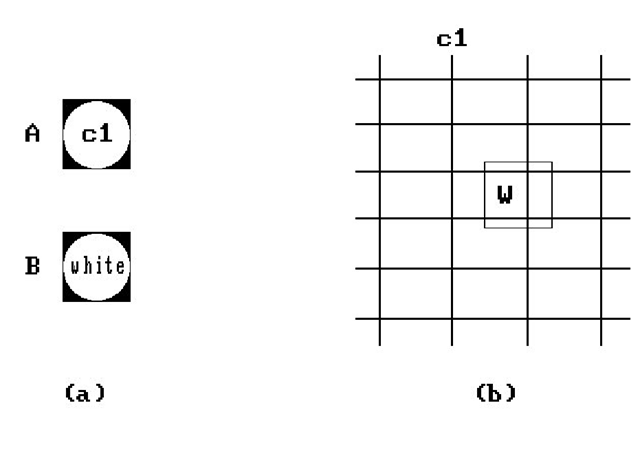
Figure 2.22. or/xor animation.
Erase the current line segment.
Draw the line segment from the fixed point to the new location of the mouse. The advantage of xoring is speed but its disadvantages are
The background can bleed through because if it is nonzero, then xor operation will add bits to the image being drawn.
One cannot xor a zero.
One can also use combinations of bit operations. Here is an example using the or/xor combination. See Figure 2.22. Suppose that one wants to move a ball around on a grid. Assume that the ball has color c1, the grid has color c2, and the background is black. Define two blocks A and B as follows: A contains a ball of color c1 on a black background and B contains a white ball on a black background. See Figure 2.22(a). If we want to write the ball to block W on the screen, we first save W and then replace W by (B or W) xor A. See Figure 2.22(b). To make this work, we need to assume that c1 and c2 are complimentary colors in the sense that
(a) c1 or c2 = white (or all 1s)
(b) c1 and c2 = black (or 0)
Actually, the only thing we really need for this technique to work in general is that the objects in the world have a different color from the object we are trying to move. The reason is that we have been talking about color numbers and the association between actual colors and their numbers is quite arbitrary and can be changed at will. This will become clear later when we talk about color lookup tables. One can play similar tricks with other bit operations such as or/and.
(6) Maintain several “pages” of information and “flip” between the pages. For example, to show a walking man, one could precompute several different walking positions of the man, and then cycle between them. Having predrawn images in memory may very well be faster than computing them dynamically.
The speed of objects depends on how far apart they are drawn in succession. A basic way to keep track of multiple moving figures is to cycle through them. One can keep track of them using arrays. If objects overlap but one knows their relative distances from the viewer one can prioritize them by distance and use a painter’s algorithm and draw the nearer objects last.
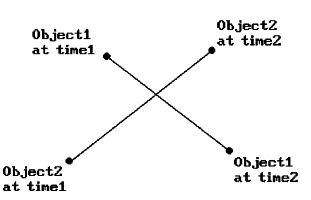
One big problem with multiple objects is collision detection. Bounding boxes may be helpful in cutting down on the amount of computation if the objects are complicated. Sometimes one knows where collisions can occur and then one only has to check in those places. One potential problem is shown in Figure 2.23 where two objects crossed paths but no collision would have been detected since one only checks for that in their final position. To handle that one could keep track of the paths of objects and check their intersections.
Now, the methods above have lots of constraints and will only work in certain situations. In (2) and (3), each figure has to fit into a block with a fixed background in that block. The methods also tend to be slow. However, in the early days of the personal computer the graphics system did not give developers much to work with. There is another issue in the case of CRTs that was alluded to briefly in Section 1.3. Writing a block of memory to the frame buffer while the hardware is scanning it and displaying the picture will usually cause flicker in the image. This is caused by the fact that the scan is much faster than the memory writes and during one scan only part of the memory block may have been written. To get flicker-free images a programmer would have to be very careful about the timing of the writes, which would usually be done during the vertical retrace of the beam. Furthermore, everything would have to be done in assembly language to get maximum speed. Fortunately, by using APIs like
Figure 2.23. A collision-detection problem.
OpenGL and DirectX, most programmers no longer have to worry about such low-level issues because those were dealt with by the implementers of those APIs.
Next, we look at another aspect of frame buffers that is very helpful for animation. Today’s frame buffers have hardware support for
(1) lookup tables
(2) panning, and
(3) zooming
Lookup Tables. Users and programmers can reference colors in different ways even though, at the hardware level, any representation eventually needs to be translated into RGB values.One standard way to reference a color is by means of a number that really is an index into a table. This table is initialized by the operating system to certain default values. The size of the table depends on the number of colors that can be displayed simultaneously by the graphics system. For example, the number 0 is the standard representative for black. For a 256-color table, the standard number for white would be 255. The actual color that the hardware can associate to an index is quite arbitrary however and can be changed by a programmer. In that way, a relatively small table can access a large number of colors. For example, even if we only have a table of size 256 (8 bits), we would be able to access an actual 24 bit worth of colors (but only 256 at a time).
Panning. The frame buffer in the graphics hardware might actually be much larger than the number of pixels on the screen. By using “origin registers” that specify the location where the electron beam starts its scan in the buffer, the hardware makes panning easy. One can quickly scroll the image up or down, or left or right, simply by changing the values in those registers.
Zooming. The zoom feature allows one to display a portion of the image in magnified form. The magnification power is typically a power of 2. What happens is that a zoom factor of, say 2, would repeat each pixel and scan line twice.
The above-mentioned features allow three interesting forms of animation.
(1) Animation using lookup tables:
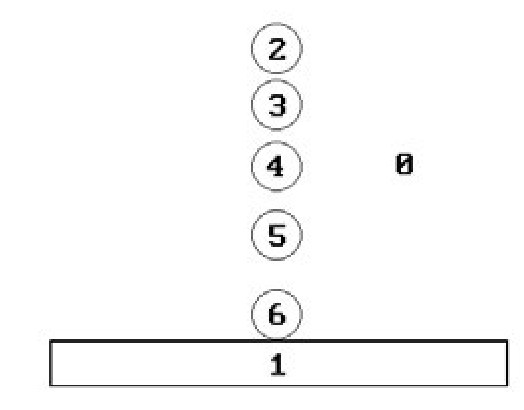
We explain this technique with an example. To show a red ball bouncing on a gray floor and a black background we could set up a picture as shown in Figure 2.24.
Figure 2.24. Bouncing ball using lookup table.
The numbers show the color numbers associated to the indicated regions. We start by associating the colors gray and red to 1 and 2, respectively, and black to all the other numbers. For the second frame we change 2 to black and 3 to red. For the third frame, we change 3 to black and 4 to red, and so on. In this way, making the ith ball the red ball as i changes from 2 to 6 and then from 6 back to 2, the ball will appear to bounce.
(2) Animation using color cycling and bit plane extraction:
Color cycling means that if we have a color table T with n entries, then we keep changing the colors of items via the instructions
If the colors in the image are designed appropriately, then these changes can create the illusion of motion.
Bit plane extraction relies on the fact that individual bits of a pixel can be thought of as corresponding to individual image bit planes. Frame buffers are then just a collection of k bit planes, where k is the number of bits in a pixel. See Figure 2.25. One trick we can now play is to create k different image frames with each frame using a subset of all colors. Then animation can be achieved by setting the lookup values for all values except the current frame value to the background color. Such updating of lookup values causes the picture to cycle through the frames. For example, assume that we have 3 bit pixels. We first set all color numbers except 4 to black, then we set all color numbers except 2 to black, and finally we set all color numbers except 1 to black. This will cycle through three single color images.
(3) Animation using the pan and zoom features:
One divides the frame buffer into k smaller areas. Typical values for k are 4 and 16. Next, one creates a reduced resolution image for a frame of animation in each area. The animation is produced by zooming each area appropriately and then cycling through the areas by changing the origin registers appropriately.
Figure 2.25. The bit planes of a frame buffer.
Comparing the second and third methods, we see that the second has full resolution but allows a limited number of colors whereas the third has low resolution but offers full use of colors.
Some graphics systems supported small fixed-size rectangular pixel blocks that are maintained separately from the frame buffer but can be superimposed on it by the hardware. These are called sprites and were common in the hardware for video games. Using sprites it is very fast to move small images around on the screen without disturbing the background simply by changing some registers that specify the address in the frame buffer at which to show the sprite. Some simple video games consisted entirely of sprites moving over a fixed background. Collisions can be checked very easily. Sprites can also be implemented in software using bitBlt operations, although this will obviously not be as fast.
Finally, to get a smooth animation sequence, one needs to generate a minimum of 10-15 frames per second but this depends on the complexity of the scene and one probably wants more like 24-30 frames per second. Aside from the fact that writing large blocks of data takes time and would slow down any animation, there is an additional problem for CRTs that we have mentioned before. One has to be very careful about when and what one writes to the frame buffer if one wants to avoid flicker. It might be much better to create a complete image in an auxiliary buffer and then copy it to the frame buffer in one fell swoop. The only problem is that the copy operation would involve so much memory that it would not be fast enough and there would still be flicker. To avoid this copying most graphics systems on PCs now support what is called double buffering, that is, the auxiliary buffer one wants to write to is actually part of the graphics system (not part of main memory) and rather than copying it to the frame buffer, the hardware allows one to switch the scanning of the electron beam between it and the initial frame buffer. The changeover becomes almost instantaneous and the flicker will be gone. Of course, if it takes too long to compute each image, then the animation would be jerky.
![tmpc646-226_thumb[2][2][2][2] tmpc646-226_thumb[2][2][2][2]](http://what-when-how.com/wp-content/uploads/2012/06/tmpc646226_thumb2222_thumb.png)
![tmpc646-228_thumb[2][2][2][2] tmpc646-228_thumb[2][2][2][2]](http://what-when-how.com/wp-content/uploads/2012/06/tmpc646228_thumb2222_thumb.png)
![tmpc646-229_thumb[2][2][2][2] tmpc646-229_thumb[2][2][2][2]](http://what-when-how.com/wp-content/uploads/2012/06/tmpc646229_thumb2222_thumb.png)
![tmpc646-230_thumb[2][2][2][2] tmpc646-230_thumb[2][2][2][2]](http://what-when-how.com/wp-content/uploads/2012/06/tmpc646230_thumb2222_thumb.png)
![tmpc646-231_thumb[2][2][2][2] tmpc646-231_thumb[2][2][2][2]](http://what-when-how.com/wp-content/uploads/2012/06/tmpc646231_thumb2222_thumb.png)
![tmpc646-232_thumb[2][2][2][2] tmpc646-232_thumb[2][2][2][2]](http://what-when-how.com/wp-content/uploads/2012/06/tmpc646232_thumb2222_thumb.png)

![tmpc646-235_thumb[2][2][2][2] tmpc646-235_thumb[2][2][2][2]](http://what-when-how.com/wp-content/uploads/2012/06/tmpc646235_thumb2222_thumb.png)
![tmpc646-236_thumb[2][2][2][2] tmpc646-236_thumb[2][2][2][2]](http://what-when-how.com/wp-content/uploads/2012/06/tmpc646236_thumb2222_thumb.png)
