Offset Shapes
Offset Curves
To offset a curve or surface traditionally means to move the original a certain distance along a normal vector. Here we are thinking of the curve or surface as lying in R3 and the normal vector being a vector in R3. One can define a more intrinsic notion, however, and the engulfing space does not have to be R3. For example, given a curve in some surface S, one can define the offset of that curve in S. This would be gotten by moving that curve along geodesics in S that are orthogonal to the original curve. Such offsets are called geodesic offsets. A good overview of the literature on offset curves and surfaces can be found in [Pham92] and [Maek99]. See also [Brec92].
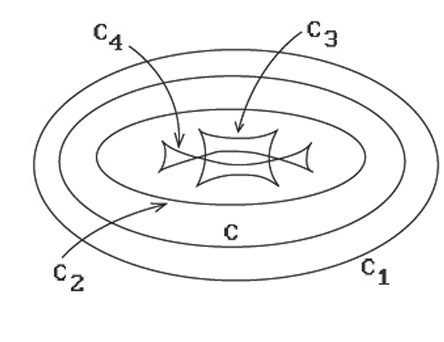
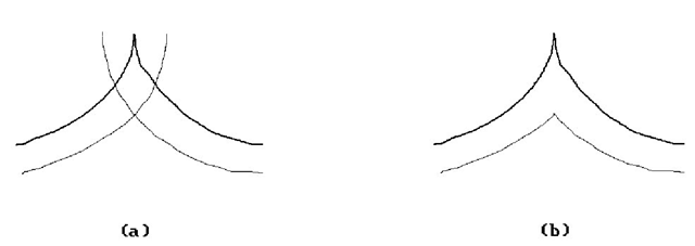
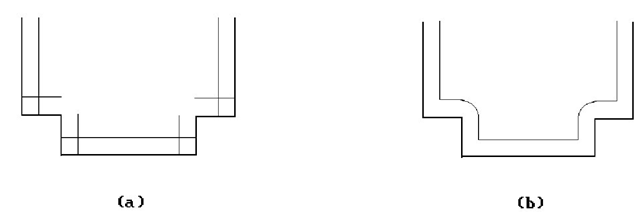
In general, getting an offset may involve stretching or shrinking the original. Figure 14.34 shows an ellipse C and four offset curves Q. Offsets are interesting also in cases where the original object is not smooth but has differentiability discontinuities. Figures 14.35(a) and 14.36(a) show offset curves when there are cusps and corners. The offsets that are probably desired are shown in Figures 14.35(b) and 14.36(b). To get them one has to do some trimming and blending.
Offset curves are in general computationally more complicated than the original curve. This is basically caused by the fact that one needs to take a square root to get a unit normal vector. For example, except for special cases, the offset of a polynomial or rational curve is not a polynomial or rational curve.
Figure 14.34. Offset curves for an ellipse.
Figure 14.35. Offset curves when there are cusps.
Figure 14.36. Offset curves when there are corners.
This section will look at some of the mathematics behind offset curves and how it can be used to solve practical problems. The reader is assumed to have familiarity with some basic differential geometry.In particular, see Section 9.7 in that topic on parallel curves (that is what offset curves are called in differential geometry) for proofs of many of the mathematical assertions made here.
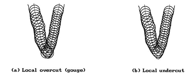
Offset curves are useful tools in a number of practical applications, such as in milling operations, tolerance analysis, and robot path planning. We shall start our discussion of analytic properties of offset curves by considering those of planar curves. This is what is relevant for describing the path of a two-axis NC machine that can move in two orthogonal directions (say the x- and y-direction). Such machines are commonly used to cut two-dimensional outlines in materials. See Figure 14.37. Two serious problems for them are local overcuts (gouging) or local undercuts. Figure 14.38(a) shows a gouging example. As described in [MaeP93], the problem is that in regions where the curvature and the signed offset distance have opposite signs, the cutter radius must be smaller than any radius of curvature of the boundary curve of the part being machined. If we simply eliminate the part of the cutter path that started and ended at the intersection point of the offset curve, then we eliminate the overcut, but will now have produced an undercut. See Figure 14.38(b).
Let![]() be a regular parameterization of a curve C in the plane. The
be a regular parameterization of a curve C in the plane. The
vector is a counter-clockwise oriented unit normal vector to this curve. ![tmp130d-31_thumb[2] tmp130d-31_thumb[2]](http://what-when-how.com/wp-content/uploads/2012/06/tmp130d31_thumb2_thumb.png)

Figure 14.37. Offset curve generated by two-axis NC machine.
Figure 14.38. NC cutter over- and undercuts.
Definition. The offset curve pd(u) to the planar curve p(u), which is a distance |d| from p(u) for some real number d is defined by
Since
where![]() is the curvature function of p(u), we see that the tangent vector to
is the curvature function of p(u), we see that the tangent vector to![]() is parallel to the tangent vector to p(u). One can also show that the curvature function for
is parallel to the tangent vector to p(u). One can also show that the curvature function for![tmp130d-38_thumb[2] tmp130d-38_thumb[2]](http://what-when-how.com/wp-content/uploads/2012/06/tmp130d38_thumb2_thumb.png) is defined by
is defined by
Its derivative with respect to arc-length parameterization is given by
Note that even if the original curve p(u) has a nice smooth shape, pd(u) may not be. In Figure 14.34, the offset curves C1 and C2 are as nice as the original ellipse. On the other hand, C3 and C4 have cusps and C4 has self-intersections on top of that. The offset curve may also intersect the original curve. Equation (14.29) points out part of the problem. Even though p(u) may be a regular curve, pd(u) will not be at those points where
There may be cusps at those points. This is only a symptom of a bigger problem, which is that a curve and its offset curve usually have different analytic types. For example, the offsets of rational curves are typically not themselves rational curves.
One often wants to talk about offset curves even when the curve is not differentiable everywhere and the normal n(u) may not be defined. See Figure 14.35(a) or 14.36(a), where we are dealing with a piecewise differentiable curve. One can deal with such problems in the case of simple isolated singularities like cusps or corners.
After this litany of problems with offset curves, let us look at approaches to dealing with them. The idea is to subdivide the domain of the curve into segments over which it and the offset behave nicely. The breakpoints of the subdivision correspond to special points on the curve for which there are tests. The points to look for are:
(1) Ordinary cusp of offset:
(2) Extraordinary cusp of offset:
(3) Turning point:
(4) Inflection point:
(5) Vertex:
The planar evolute of the curve is relevant here because one can show that the cusps of an offset lie on the evolute of the original curve (Theorem 9.7.1 in [AgoM05]). The planar evolute is the locus of the centers of curvature and is defined by
The special points defined by (3-5) above (called characteristic points in [FarN90a]) are “intrinsic” properties of curves because they involve solving for zeros of![]()
![tmp130d-52_thumb[2] tmp130d-52_thumb[2]](http://what-when-how.com/wp-content/uploads/2012/06/tmp130d52_thumb2_thumb.png) These points are interesting on both curves, but one can show that the turning points, inflection points, and vertices of the offset curve correspond to those of the original curve, except that if
These points are interesting on both curves, but one can show that the turning points, inflection points, and vertices of the offset curve correspond to those of the original curve, except that if![]() at a turning point or vertex of p(u), then the corresponding point on pd(u) is a cusp or an extraordinary cusp. See Theorem 9.7.2 in [AgoM05].
at a turning point or vertex of p(u), then the corresponding point on pd(u) is a cusp or an extraordinary cusp. See Theorem 9.7.2 in [AgoM05].
After the special points (1-5) above have been found one has a segmentation of the curve and its offset. The curve can then be approximated over each primitive segment in a suitable way, say by some polygonal curves. One is not yet done though because trimming needs to be done if there are self-intersections in the offset curve. This involves first finding the intersection points, an interesting problem in its own right, and then trimming the segments between them. See [FarN90a]. One is then finally ready to generate an appropriate path for the NC machine.
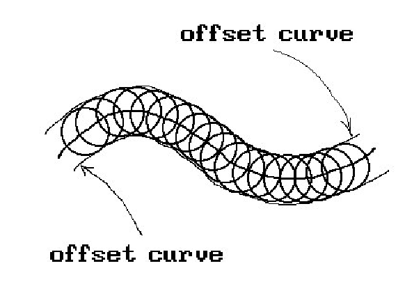
Another approach to getting offset curves is suggested by how milling machines work. One rolls a circle of radius d along the curve. This will sweep out a solid region and the offset curve is one of the boundaries of that region. See Figure 14.39. Now the circle of radius d centered at p(u) can be parameterized by
The points on the offset curve are therefore those at which the tangent line to![tmp130d-58_thumb[2] tmp130d-58_thumb[2]](http://what-when-how.com/wp-content/uploads/2012/06/tmp130d58_thumb2_thumb.png) ) is parallel to the tangent line at
) is parallel to the tangent line at![]() In other words, we are looking for those points at which
In other words, we are looking for those points at which
that is,
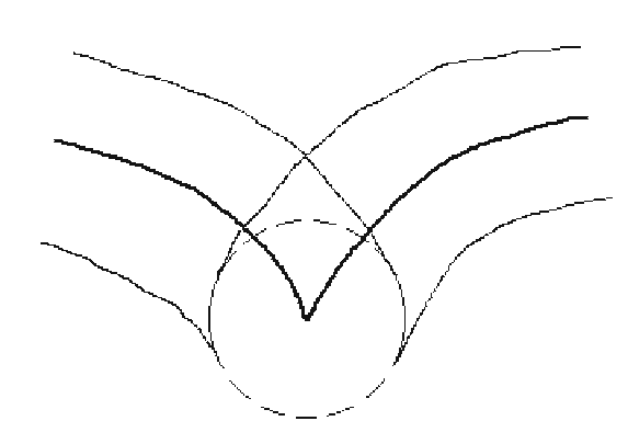
One has to worry about those places where y’(u) is zero, in particular, where there are cusps. See Figure 14.40.
The fact that equations (14.33) and (14.34) involve transcendental functions may not be desirable. Therefore, one may want to reformulate the envelope into a polynomial form by introducing two variables s and t as follows:
Figure 14.39. Offset curves from milling machine.
Figure 14.40. A milling machine offset curve problem.
Figure 14.41. Offset curves for multi-axes milling machines.
Condition (14.34) then translates into the constraint that the tangent vector is orthogonal to the radius vector, namely,
As a final application involving offset curves, consider the problem of milling freeform surfaces. This sort of operation requires minimally a three-axis milling machine that can move in three orthogonal directions. See Figure 14.41(a). Better yet is a five-axis milling machine that has an additional two degrees of freedom to allow rotations specified by two angles. See Figure 14.41(b). In any case, to carry out the milling, one can first mill along the boundary curves of the patch. Then along an offset curve in the interior of the patch that is an offset of the boundary. We can continue this way until the whole surface is milled. This process involves defining offset curves for space curves. This time we do not have well-defined normals to offset along since there is a whole normal plane at each point of the curve. However, if we look at circles of radius d in these normal planes, what we want is that the offset curve intersects that circle at some point. It is not hard to write down the appropriate equations.
Next, let p(u) be a space curve and (T(u),N(u),B(u)) its Frenet frame. The principal normal N(u) and binormal B(u) form an orthonormal basis for the normal plane to the curve at p(u).
Definition. An offset curve pd(u) to the space curve p(u) at a distance![tmp130d-69_thumb[2] tmp130d-69_thumb[2]](http://what-when-how.com/wp-content/uploads/2012/06/tmp130d69_thumb2_thumb.png) from p(u) is defined by an equation of the form
from p(u) is defined by an equation of the form
where Θ is a function of u in general.
Approaches to computing offset curves for a surface patch parameterized by a function p(u,v) are discussed in [HosL93]. One practical problem with the formulation above is that the principal normal and binormal are not easy to compute.
This concludes our discussion of offset curves. For additional facts see [FarN90a], [FarN90b], or [MaeP93]. Offsets of clothoidal splines are discussed in [MeeW90]. For an overview of a different approach, where one tries to approximate the offset rather than represent it exactly, see [ElLK97]. The motivation is that working with approximations is not as computationally expensive. The analysis of different algorithms in [ElLK97] showed that the one described in [TilH84] performed best on piecewise quadratic curves. The question of which curves have rational offsets has also been studied in various papers, because otherwise one is basically only left with approximations. For more information about this subject see [Faro92], [Pott95], [Lu95], or [FarS95].
Offset Surfaces
We have already talked about offset-type surfaces when we considered bump mappings in Section 9.8. Here we give a few definitions and state some properties of the basic offset surfaces.
Suppose that p(u,v) is a regular parameterization for a surface S. If p(u,v) is differentiable, then
is the standard normal vector to the surface. Since N(u,v) does not vanish,
is a well-defined unit normal vector to![tmp130d-74_thumb[2] tmp130d-74_thumb[2]](http://what-when-how.com/wp-content/uploads/2012/06/tmp130d74_thumb2_thumb.png) Let d be any nonzero real number.
Let d be any nonzero real number.
Definition. The offset surface![tmp130d-75_thumb[2] tmp130d-75_thumb[2]](http://what-when-how.com/wp-content/uploads/2012/06/tmp130d75_thumb2_thumb.png) which is a distance |d| from p(u,v) is
which is a distance |d| from p(u,v) is
Offset surfaces are called parallel surfaces in differential geometry. Just as in the case of offset curves, the reader is assumed to have familiarity with some basic differential geometry. The relevant material for this section can be found in Section 9.14 in [AgoM05] along with proofs of many of the mathematical assertions made here.
There are formulas that express the basic intrinsic geometric properties of an offset surface in terms of the corresponding properties of the original surface. We list them here. First of all, the normal vector
to the surface![tmp130d-80_thumb[2] tmp130d-80_thumb[2]](http://what-when-how.com/wp-content/uploads/2012/06/tmp130d80_thumb2_thumb.png) is given by the following formula
is given by the following formula
where K and H are the Gauss and mean curvature of S, respectively. Let
and define![tmp130d-84_thumb[2] tmp130d-84_thumb[2]](http://what-when-how.com/wp-content/uploads/2012/06/tmp130d84_thumb2_thumb.png) Notice that σ may equal -1 because the orientation of the offset surface may not be the same as that of the original surface. The principal normal curvatures (kj)d for the offset surface are given by
Notice that σ may equal -1 because the orientation of the offset surface may not be the same as that of the original surface. The principal normal curvatures (kj)d for the offset surface are given by
The Gauss curvature Kd and mean curvature Hd of the offset surface can be computed by
and
Clearly, all the problems that could arise in the context of offset curves are magnified for offset surfaces. There could again be cusps. We could have ridges and, of course, complicated self-intersections. Regions of high curvature and where the offset distance is close to the minimum concave radius of curvature cause problems. Barnhill and Frost ([BarF95]) analyzed three approaches to offset surfaces via approximations based on uniform bicubic Hermite meshes, NURBS surfaces, and uniform bicubic/biquintic Bezier meshes and then proposed a solution that used triangular Bernstein-Bezier patches. Other approaches for NURBS can be found in [KuSP02] and [KuSP03].
Forsyth ([Fors95]) discusses offsetting and the closely related operation of shelling in a slightly different context. Offsetting is thought of here as an operation on a solid model that adds or removes a uniform layer to its boundary. Shelling comes in two forms. Closed shelling is where one removes all of the interior of a solid further than a given distance from its boundary. In open shelling one removes all of the solid further than a given distance from a part of its boundary. Figure 14.42 shows two- dimensional examples of these operations. Clearly, shelling can be defined in terms of standard offset operations. Forsyth describes how to define such offsetting operations for the boundary representation of solids.
Figure 14.42. Shelling.
Envelopes
Envelopes are spaces that are a generalization of offset curves or surfaces. These spaces arise from the boundary of regions swept out by moving parts of machinery. Understanding the geometry of envelopes is therefore important in the design of machinery and its operation, such as in the case of NC machines or robots. In particular, it is relevant in making sure that there is adequate clearance of these parts in the work environment. Envelopes have mostly been studied when one is sweeping circles, planes, and spheres. Even there the analysis can get very tricky. A discussion of general envelopes can be found in [Brec92].
Here is a definition for envelopes in the plane.
Definition. Let![]() be a one-parameter family of curves in the plane defined by
be a one-parameter family of curves in the plane defined by![]() function
function![]() An envelope of this family is defined to be a curve p(u) that is not a member of this family but which is tangent to some member of the family at every point.
An envelope of this family is defined to be a curve p(u) that is not a member of this family but which is tangent to some member of the family at every point.
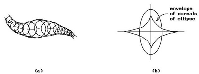
Figure 14.43(a) shows a nicely structured envelope. Figure 14.43(b) shows the envelope of normals to an ellipse whose ends are the centers of the osculating circles. In other words, an envelope can have bad singularities even if we start with nice functions.
One approach to studying the envelope p(u) is to think of p(u) as being the limit as e approaches 0 of the intersections of p(u) and p(u+e). Although this has serious problems in general, it seems to work in many cases of interest.
Figure 14.43. Envelopes of curves and normals.
![tmp130d-42_thumb[2] tmp130d-42_thumb[2]](http://what-when-how.com/wp-content/uploads/2012/06/tmp130d42_thumb2_thumb.png)
![tmp130d-43_thumb[2] tmp130d-43_thumb[2]](http://what-when-how.com/wp-content/uploads/2012/06/tmp130d43_thumb2_thumb.png)
![tmp130d-45_thumb[2] tmp130d-45_thumb[2]](http://what-when-how.com/wp-content/uploads/2012/06/tmp130d45_thumb2_thumb.png)
![tmp130d-46_thumb[2] tmp130d-46_thumb[2]](http://what-when-how.com/wp-content/uploads/2012/06/tmp130d46_thumb2_thumb.png)
![tmp130d-47_thumb[2] tmp130d-47_thumb[2]](http://what-when-how.com/wp-content/uploads/2012/06/tmp130d47_thumb2_thumb.png)
![tmp130d-48_thumb[2] tmp130d-48_thumb[2]](http://what-when-how.com/wp-content/uploads/2012/06/tmp130d48_thumb2_thumb.png)
![tmp130d-49_thumb[2] tmp130d-49_thumb[2]](http://what-when-how.com/wp-content/uploads/2012/06/tmp130d49_thumb2_thumb.png)
![tmp130d-50_thumb[2] tmp130d-50_thumb[2]](http://what-when-how.com/wp-content/uploads/2012/06/tmp130d50_thumb2_thumb.png)
![tmp130d-63_thumb[2] tmp130d-63_thumb[2]](http://what-when-how.com/wp-content/uploads/2012/06/tmp130d63_thumb2_thumb.png)

![tmp130d-67_thumb[2] tmp130d-67_thumb[2]](http://what-when-how.com/wp-content/uploads/2012/06/tmp130d67_thumb2_thumb.png)
![tmp130d-72_thumb[2] tmp130d-72_thumb[2]](http://what-when-how.com/wp-content/uploads/2012/06/tmp130d72_thumb2_thumb.png)
![tmp130d-73_thumb[2] tmp130d-73_thumb[2]](http://what-when-how.com/wp-content/uploads/2012/06/tmp130d73_thumb2_thumb.png)
![tmp130d-79_thumb[2] tmp130d-79_thumb[2]](http://what-when-how.com/wp-content/uploads/2012/06/tmp130d79_thumb2_thumb.png)
![tmp130d-83_thumb[2] tmp130d-83_thumb[2]](http://what-when-how.com/wp-content/uploads/2012/06/tmp130d83_thumb2_thumb.png)
![tmp130d-86_thumb[2] tmp130d-86_thumb[2]](http://what-when-how.com/wp-content/uploads/2012/06/tmp130d86_thumb2_thumb.png)
![tmp130d-87_thumb[2] tmp130d-87_thumb[2]](http://what-when-how.com/wp-content/uploads/2012/06/tmp130d87_thumb2_thumb.png)
![tmp130d-88_thumb[2] tmp130d-88_thumb[2]](http://what-when-how.com/wp-content/uploads/2012/06/tmp130d88_thumb2_thumb.png)

