Introduction
This topic describes some often-used mathematical tools and formulas in geometric modeling. The author highly recommends the Graphics Gems series of topics to the reader (see the "Miscellaneous" section of the Bibliography). These topics contain many insights into how one can make computations and algorithms more efficient.
We begin by discussing bounding objects, such as boxes, slabs, and spheres, and their uses in Section 6.2. Next, in Section 6.3 we look at tests for when a point is inside a region. Section 6.4 describes some facts that, in one way or another, are related to orientation. Some simple intersection algorithms are discussed in Section 6.5. Section 6.6 has some formulas for distances between objects, Section 6.7 has area and volume formulas, and Section 6.8 has formulas for circle constructions. We finish the topic with some miscellaneous observations in Sections 6.9 and 6.10.
Bounding Objects and Minimax Tests
Checking for or finding intersections, as for example in clipping, visible surface determination, and collision detection, is a frequently performed task in graphics. It is also one that is usually very computation intensive, even for simple objects like polygons. Now, if complicated objects intersect, then one has to accept the fact that finding this intersection will take a lot of work. On the other hand, to make lengthy computations only to find out in the end that the objects do not intersect is very inefficient. One would like a quicker way to detect when objects are disjoint. A standard way to do this is to enclose objects in simpler ones and first check for intersections among these simpler objects. If they do not intersect, then by definition, the original objects will not intersect. If they do intersect, well, then we will have to bite the bullet and check out the original objects.
Definition. A bounding object for an object A is any object B that contains A.
This section looks at some common types of bounding objects. Keep in mind the following three desirable properties that bounding objects should possess:
(1) They should be easy to compute.
(2) It should be easy to tell if they intersect.
(3) They should “fit” an object fairly closely.
The motivation behind property (3) is that we are trying to detect disjointness quickly, and the bigger that bounding objects are the more they will intersect, forcing us into lengthy computations we are trying to avoid. For an analysis as to whether bounding objects are really worth it see [SuHH99] and [ZhoS99].
Definition. A box in Rn is any subset of the form
where![]() (It is convenient here to think of
(It is convenient here to think of![]() as segments and not require that
as segments and not require that![]() A bounding box for an object is a box that contains the object.
A bounding box for an object is a box that contains the object.
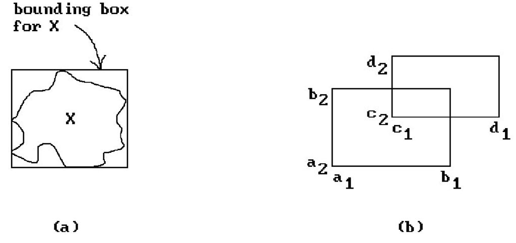
Figure 6.1(a) shows a bounding box. It is easy to check for intersections of bounding boxes. For example, two segments [ai,bi] and [a2,b2] intersect if and only if
and if they intersect, then the intersection is the interval
Notice how this formula shows that![]() In
In
general, we have
Figure 6.1. Bounding boxes.
Theorem. The boxes
will intersect if and only if
for all i. If they intersect, then
Proof. Easy. See Figure 6.1(b).
For obvious reasons, the intersection test in Theorem 6.2.1 is usually called the minimax test.
A bounding box for a polygon can be defined from the minimum and maximum values of all the coordinates of its vertices. Looking ahead, the bounding box for a spline curve or surface is usually taken to be a bounding box for its control points. (This uses the important fact that splines lie in the convex hull of their control points.) Other objects may have to have their bounding boxes defined by hand.
Bounding boxes are probably the most common bounding objects that are used because it is so easy to work with them, but they are far from perfect. The main problem is that they may be a bad fit to the object. For example, the best bounding box for a line segment has that line segment as a diagonal. It is clearly easy to find lots of other objects for which rectangular boxes are a bad fit. For that reason, other bounding objects may be more appropriate for any given world of objects. There is nothing to keep us from using different types of bounding objects within one program to optimize fits. Unfortunately though, usually the better the fit, the more complicated it is to compute intersections.
A natural way to generalize bounding boxes is to allow bounding faces to be slanted and not just horizontal or vertical.
Definition. A slab in Rn is the region between two parallel hyperplanes.
Given a bounded set X, a unit vector n determines a slab as follows: Starting arbitrarily far out on the two ends of the line through the origin with direction vector n, slide two hyperplanes orthogonal to n towards the origin until they touch X.
Definition. The region between the two touching planes is called the slab for X induced by the unit vector n and is denoted by Slab(X,n).
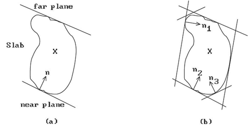
See Figure 6.2(a). The two hyperplanes that bound the slab Slab(X,n) can be written in the form
where The plane that corresponds to the
![]() will be called the near
will be called the near
plane for the slab and the other one, the far plane. Note that if we were to project X orthogonally to the line through the origin with direction vector n, then X would project onto the segment![]()
We can use more than one vector n.
Figure 6.2. Bounding slabs.
Definition. The generalized bounding box for X determined by a fixed set,![]()
![]() of unit vectors is the intersection of the slabs that they determine. More precisely, if we denote this set by
of unit vectors is the intersection of the slabs that they determine. More precisely, if we denote this set by![]() then
then
See Figure 6.2(b). These parallelopiped-type boxes were introduced by [KayK86]. It turns out that they are not much more complicated to work with than simple boxes.
First of all, we show how the generalized bounding boxes are determined for three different types of objects in R3. Note that all we have to find is the
Linear Polyhedra. In this case we project all of its vertices pj onto the ni and use the minimum and maximum of those values, that is,
Implicitly Defined Surfaces. Assume that a surface S is defined by an equation
The will be the minimum and maximum, respectively, of the linear function
 subject to the constraint above. These values can be solved for using the method of Lagrange multipliers.
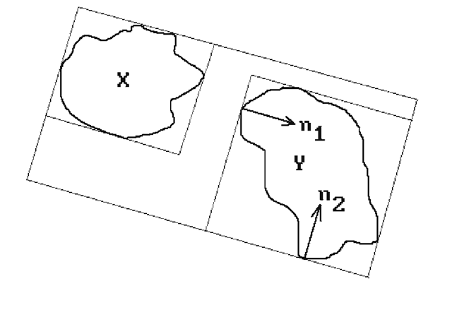
Compound Objects. Assume that an object is defined by successive application of the operations of union, intersection, and difference of two objects starting with primitive objects of the type above. The dnear and dfar of the result is easily computed in terms of the dnear and dfar of the primitives that define it. For example, to get the dnear and dfar of the union of two objects X and Y, we need simply take the minimum of the two given dnear and the maximum of the two given dfar. See Figure 6.3.
Figure 6.3. Combining bounding boxes.
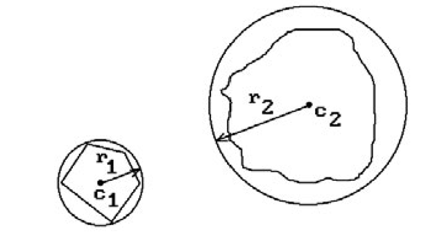
Figure 6.4. Bounding spheres.
Finding the intersection B of two generalized bounding boxes Bi and B2 (defined with respect to the same set of normal vectors) is not hard. The formulas are really the same as those for boxes. The only difference is that instead of taking maxima and minima of coordinates (the orthogonal projections onto the standard axes ei) we now take maxima and minima of the orthogonal projections onto the normals ni, that is,
The generalized boxes B1 and B2 are disjoint if and only if for somei.
Other common types of bounding object are circles or spheres (we shall use the generic term “sphere” to refer to both). Such bounding spheres are also easy to deal with and may fit the objects better. See Figure 6.4. Two spheres Si with centers ci and radii ri will intersect if and only if
Finding the appropriate bounding sphere for an object is usually not hard if done by hand. Automating the process is not quite so easy. It involves finding the smallest sphere containing a set or n points. There are optimal O(n) algorithms known for doing this using Voronoi diagrams. See [PreS85].


