Analog Address Signaling
The dialing phase allows the subscriber to enter a phone number (address) of a telephone at another location. The customer enters this number with either a rotary phone that generates pulses or a touch-tone (push-button) phone that generates tones. Table 3-2 shows the frequency tones generated by dual tone multifrequency (DTMF) dialing.
Table 3-2 DTMF Frequencies
|
Frequencies |
1209 |
1336 |
1477 |
|
697 |
1 |
2 |
3 |
|
770 |
4 |
5 |
6 |
|
852 |
7 |
8 |
9 |
|
941 |
 |
0 |
 |
Telephones use two different types of address signaling to notify the telephone company where a subscriber calls:
■ Pulse dialing
■ DTMF dialing
These pulses or tones are transmitted to the CO switch across a two-wire twisted-pair cable (tip and ring lines). On the voice gateway, the FXO port sends address signaling to the FXS port. This address indicates the final destination of a call.
Pulsed tones were used by the old rotary phones. These phones had a disk that was rotated to dial a number. As the disk rotated, it opened and closed the circuit a specified number of times based on how far the disk was turned. The exchange equipment counted those circuit interruptions to determine the called number. The duration of open-to-closed times had to be within specifications according to the country you were in.
These days, analog circuits use DTMF tones to indicate the destination address. DTMF assigns a specific frequency (consisting of two separate tones) to each key on the touch-tone telephone dial pad. The combination of these two tones notifies the receiving subscriber of the digits dialed.
Informational Signaling
The FXS port provides informational signaling using call progress (CP) tones, as detailed in Table 3-3. These CP tones are audible and are used by the FXS connected device to indicate the status of calls.
Table 3-3 Network Call Progress Tones
|
Tone |
Frequency(Hz) |
On Time (sec) |
Off Time (sec) |
|
Dial |
350 + 440 |
Continuous |
Continuous |
|
Busy |
480 + 620 |
0.5 |
0.5 |
|
Ringback, line |
440 + 480 |
2 |
4 |
|
Ringback, PBX |
440 + 480 |
1 |
3 |
|
Congestion (toll) |
480 + 620 |
0.2 |
0.3 |
|
Reorder (local) |
480 + 620 |
0.3 |
0.2 |
|
Receiver off-hook |
1400 + 2060 + 2450 + 2600 |
0.1 |
0.1 |
|
No such number |
200 to 400 |
Continuous |
Continuous |
The progress tones listed in Table 3-3 are for North American phone systems.
International phone systems can have a totally different set of progress tones. Users should be familiar with most of the following call progress tones:
■ Dial tone: Indicates that the telephone company is ready to receive digits from the user telephone.
■ Busy tone: Indicates that a call cannot be completed because the telephone at the remote end is already in use.
■ Ring-Back (normal or PBX): Tone indicates that the telephone company is attempting to complete a call on behalf of a subscriber.
■ Congestion: Progress tone is used between switches to indicate that congestion in the long-distance telephone network currently prevents a telephone call from being processed.
■ Reorder: Tone indicates that all the local telephone circuits are busy and thus prevents a telephone call from being processed.
■ Receiver off-hook: Tone is the loud ringing that indicates the receiver of a phone is left off-hook for an extended period of time.
■ No such number: Tone indicates that the number dialed cannot be found in the routing table of a switch.
E&M Signaling
E&M is another signaling technique used mainly between PBXs or other network-to-network telephony switches (Lucent 5 Electronic Switching System [5ESS], Nortel DMS-100, and so on). E&M signaling supports tie-line type facilities or signals between voice switches. Instead of superimposing both voice and signaling on the same wire, E&M uses separate paths, or leads, for each.
There are six distinct physical configurations for the signaling part of the interface. They are Types I-V and Signaling System Direct Current No.5 (SSDC5). They use different methods to signal on-hook or off-hook status, as shown Table 3-4. Cisco voice implementation supports E&M Types I, II, III, and V.
Table 3-4 E&M Signaling Types
|
Type |
M-Lead Off-Hook |
M-Lead On-Hook |
E-Lead Off-Hook |
E-Lead On-Hook |
|
I |
Battery |
Ground |
Ground |
Open |
|
II |
Battery |
Open |
Ground |
Open |
|
III |
Loop Current |
Ground |
Ground |
Open |
|
IV |
Ground |
Open |
Ground |
Open |
|
V |
Ground |
Open |
Ground |
Open |
|
SSDC5 |
Earth On |
Earth Off |
Earth On |
Earth Off |
The following list details the characteristics of each E&M signaling type introduced in Table 3-4:
■ Type I: Type I signaling is the most common E&M signaling method used in North America. One wire is the E lead. The second wire is the M lead, and the remaining two pairs of wires serve as the audio path. In this arrangement, the PBX supplies power, or battery, for both E and M leads. In the idle (on-hook) state, both the E and M leads are open. The PBX indicates an off-hook by connecting the M lead to the battery. The line side indicates an off-hook by connecting the E lead to ground.
■ Type II: Type II signaling is typically used in sensitive environments because it produces very little interference. This type uses four wires for signaling. One wire is the E lead. Another wire is the M lead, and the two other wires are signal ground (SG) and signal battery (SB). In Type II, SG and SB are the return paths for the E lead and M lead, respectively. The PBX side indicates an off-hook by connecting the M lead to the SB lead. The line side indicates an off-hook by connecting the E lead to SG lead.
■ Type III: Type III signaling is not commonly used. Type III also uses four wires for signaling. In the idle state (on-hook), the E lead is open and the M lead is connected to the SG lead, which is grounded. The PBX side indicates an off-hook by moving the M lead from the SG lead to the SB lead. The line side indicates an off-hook by grounding the E lead.
■ Type IV: Type IV also uses four wires for signaling. In the idle state (on-hook), the E and M leads are both open. The PBX side indicates an off-hook by connecting the M lead to the SB lead, which is grounded on the line side. The line side indicates an off-hook by connecting the E lead to the SG lead, which is grounded on the PBX side.
Note E&M Type IV is not supported on Cisco voice gateways. However, Type IV operates similarly to Type II except for the M-lead operation. On Type IV, the M-lead states are open/ground, compared to Type II, which is open/battery. Type IV can interface with Type II. To use Type IV you can set the E&M voice port to Type II and perform the necessary M-lead rewiring.
■ Type V: Type V is the most common E&M signaling form used outside of North America. Type V is similar to Type I because two wires are used for signaling (one wire is the E lead and the other wire is the M lead). In the idle (on-hook) state, both the E and M leads are open as in the preceding diagram. The PBX indicates an off-hook by grounding the M lead. The line side indicates an off-hook by grounding the E lead.
■ SSDC5: Similar to Type V, SSDC5 differs in that on- and off-hook states are backward to allow for fail-safe operation. If the line breaks, the interface defaults to off-hook (busy). SSDC5 is most often found in England.
E&M Physical Interface
The physical E&M interface is an RJ-48 connector that connects to PBX trunk lines,which are classified as either two-wire or four-wire.
Note Two-wire and four-wire refer to the voice wires. A connection might be called a four-wire E&M circuit although it actually has six to eight physical wires.
Two or four wires are used for signaling, and the remaining two pairs of wires serve as the audio path. This refers to whether the audio path is full duplex on one pair of wires (two-wire) or on two pairs of wires (four-wire).
E&M Address Signaling
PBXs built by different manufacturers can indicate on-hook/off-hook status and telephone line seizure on the E&M interface by using any of three types of access signaling:
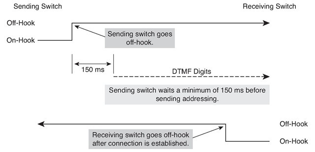
■ Immediate-start: Immediate-start, as illustrated in Figure 3-12, is the simplest method of E&M access signaling. The calling side seizes the line by going off-hook on its E lead, waits for a minimum of 150 ms and then sends address information as DTMF digits or as dialed pulses. This signaling approach is used for E&M tie trunk interfaces.
Figure 3-12 Immediate-Start Signaling
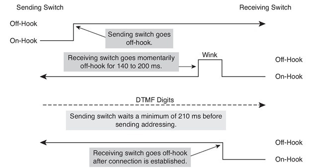
■ Wink-start: Wink-start, as shown in Figure 3-13, is the most commonly used method for E&M access signaling and is the default for E&M voice ports. Wink-start was developed to minimize glare, a condition found in immediate-start E&M, in which both ends attempt to seize a trunk at the same time. In wink-start, the calling side seizes the line by going off-hook on its E lead; it then waits for a short temporary off-hook pulse, or "wink," from the other end on its M lead before sending address information as DTMF digits. The switch interprets the pulse as an indication to proceed and then sends the dialed digits as DTMF or dialed pulses. This signaling is used for E&M tie trunk interfaces. This is the default setting for E&M voice ports.
Figure 3-13 Wink-Start Signaling
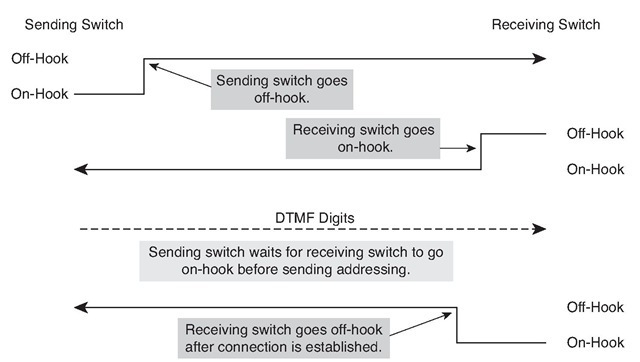
■ Delay-start: With delay-start signaling, as depicted in Figure 3-14, the calling station seizes the line by going off-hook on its E lead. After a timed interval, the calling side looks at the status of the called side. If the called side is on-hook, the calling side starts sending information as DTMF digits. Otherwise, the calling side waits until the called side goes on-hook and then starts sending address information. This signaling approach is used for E&M tie trunk interfaces.
Figure 3-14 Delay-Start Signaling
Configuring Analog Voice Ports
The three types of analog ports that you will learn to configure are
■ FXS
■ FXO
■ E&M


