SIP Gateway Configuration Procedure
The following procedure describes how to configure a SIP gateway as per network requirements:
Step 1. Enter voice-service configuration mode and specify VoIP as the voice-encapsulation type.
Step 2. Enter SIP configuration mode.
Step 3. Specify SIP parameters.
Specify the underlying transport layer protocol for SIP messages, and bind the source address for signaling and media packets to the IP address of a specific interface.
If the bind command is not enabled, the IP layer still provides the best local address.
Step 4. Exit SIP configuration mode.
Step 5. Activate the voice service.
Step 6. Enter SIP UA configuration mode.
Step 7. Configure Digest Authentication.
Step 8. Enable the SIP gateway to register E.164 numbers on behalf of analog telephone voice ports (FXS), IP phone virtual voice ports (EFXS), and SCCP phones with an external SIP proxy or SIP registrar.
Step 9. Enter the hostname or IP address of the SIP server interface.
If you use this command, you can specify session target sip-server for each dial peer instead of repeatedly entering the SIP server interface address for each dial peer.
Step 10. Adjust the SIP parameters per network requirements.
The complete configuration for these steps is presented in Example 5-14.
Example 5-14 Integrating IOS Gateways with a SIP ITSP
SIP Dial-Peer Example
SIP is selected as the call control protocol from inside a dial peer. SIP is requested by the session protocol sipv2 dial-peer subcommand.
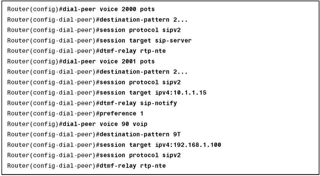
In this example, both dial peers include the session protocol sipv2 subcommand, and SIP is used when the destination pattern matches either dial peer. The session target distinguishes one session from the other.
In dial-peer 999, the IP address of the server is provided as the session target. The address can be the address of a UA, proxy server, or redirect server.
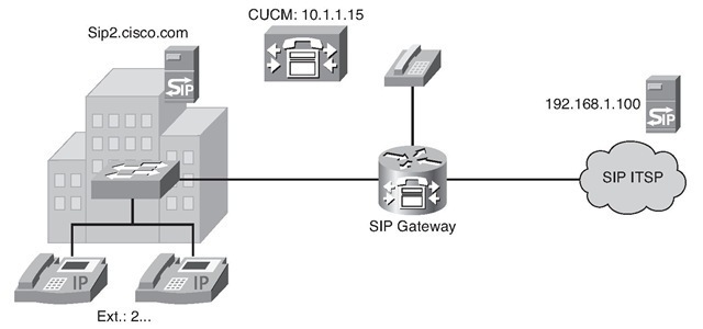
In dial-peer 200, the session target is the sip-server parameter. When the sip-server parameter is the target, the IP address of the actual server is taken from the sip-server subcommand in the SIP UA configuration. This means that from global configuration mode, the network administrator has entered the sip-ua command and the sip-server dns:server subcommand. The address represents the location of a proxy server or redirect server. In this example, the name of the SIP server is "sip2.cisco.com." The dial peer must know how to deal with DTMF signals. The following example uses the dtmf-relay sip-notify command used for sending telephone-event notifications via SIP NOTIFY messages from a SIP gateway.
The topology and complete configuration for this scenario are presented in Figure 5-31 and in Example 5-15.
Figure 5-31 SIP Dial-Peer Topology Example
Example 5-15 SIP Dial-Peer Configuration Example
Verifying SIP Gateways
The show commands listed in Table 5-2 are valuable when examining the status of SIP components and troubleshooting SIP environments.
Table 5-2 SIP show Commands
|
Command |
Description |
|
show sip service |
Displays the status of the SIP VoIP service |
|
show sip-ua status |
Displays the status of the SIP UA |
|
show sip-ua register status |
Displays the status of E.164 numbers that a SIP gateway has |
|
registered with an external primary SIP registrar |
|
|
show sip-ua timers |
Displays SIP UA timers |
|
show sip-ua connections |
Displays active SIP UA connections |
|
show sip-ua calls |
Displays active SIP UA calls |
|
show sip-ua statistics |
Displays SIP traffic statistics |
Use the show sip service command to display the status of SIP call service on a SIP gateway. Example 5-16 provides sample output from the show sip service command.
Example 5-16 show sip service Command
Use the show sip-ua status command to display the status for the SIP user agent, including whether call redirection is enabled or disabled. Example 5-17 provides sample output from the show sip-ua status command.
Example 5-17 show sip-ua status Command
Use the show sip-ua timers command to display the current settings for the SIP user-agent timers. Example 5-18 provides sample output from the show sip-ua timers command.
Example 5-18 show sip-ua timers Command
Use the show sip-ua register status command to display the status of E.164 numbers that a SIP gateway has registered with an external primary SIP registrar. Example 5-19 provides sample output from the show sip-ua register status command.
Example 5-19 show sip-ua register status Command
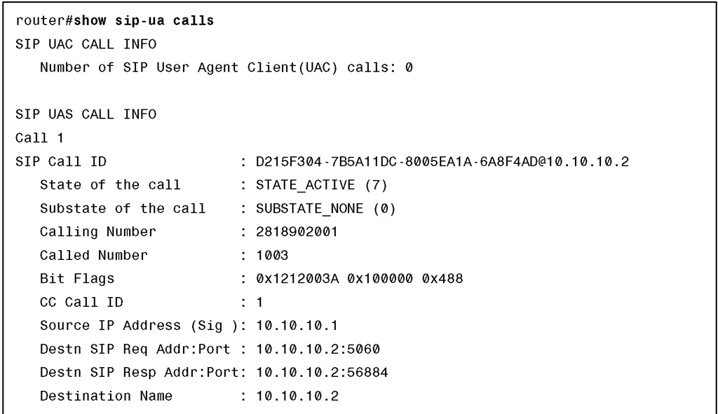
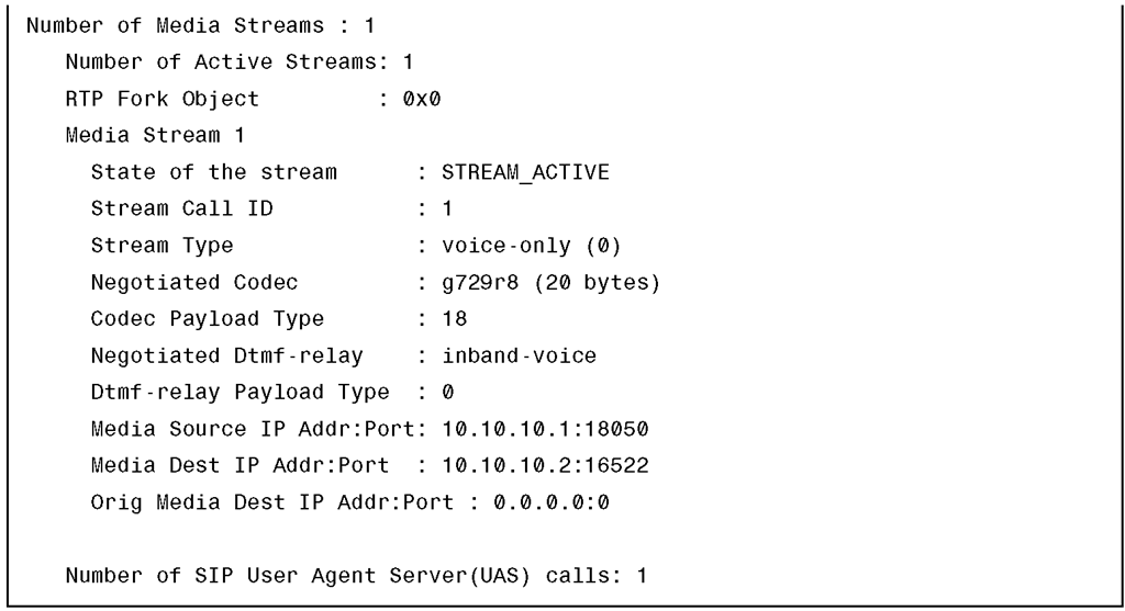
Example 5-20 shows the output of the show sip-ua calls command, which provides detailed information about current SIP calls.
Example 5-20 show sip-ua calls Command
Example 5-20 show sip-ua calls Command
The following debug commands are valuable when examining the status of SIP components and troubleshooting SIP environments:
■ debug asnl events: Use this command to verify that the SIP subscription server is up. The output displays a pending message if, for example, the client is unsuccessful in communicating with the server.
■ debug voip ccapi inout: This command shows every interaction with the call control API on both the telephone interface and on the VoIP side. By monitoring the output, you can follow the progress of a call from the inbound interface or VoIP peer to the outbound side of the call. This debug command is very active. Therefore, you must use it sparingly in a live network.
■ debug voip ccapi protoheaders: This command displays messages sent between the originating and the terminating gateways. If no headers are being received by the terminating gateway, verify that the header-passing command is enabled on the originating gateway.
■ debug ccsip all: This command enables all ccsip-type debugging. This debug command is very active. Therefore, you should use it sparingly in a live network.
■ debug ccsip calls: This command displays all SIP call details as they are updated in the SIP call control block. You can use this debug command to monitor call records for suspicious clearing causes.
■ debug ccsip errors: This command traces all errors encountered by the SIP subsystem.
■ debug ccsip events: This command traces events, such as call setups, connections, and disconnections. An events version of a debug command is often the best place to start because detailed debugs provide a great deal of useful information.
■ debug ccsip info: This command enables tracing of general SIP Service Provider Interface (SPI) information, including verification that call redirection is disabled.
■ debug ccsip media: This command enables tracing of SIP media streams.
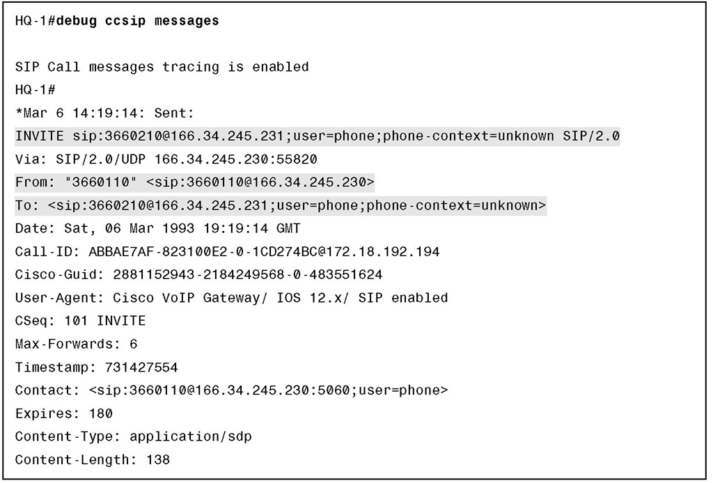
■ debug ccsip messages: This command shows the headers of SIP messages that are exchanged between a client and a server.
■ debug ccsip preauth: This command enables diagnostic reporting of authentication, authorization, and accounting (AAA) for SIP calls.
■ debug ccsip states: This command displays the SIP states and state changes for sessions within the SIP subsystem.
■ debug ccsip transport: This command enables tracing of the SIP transport handler and the TCP or UDP process.
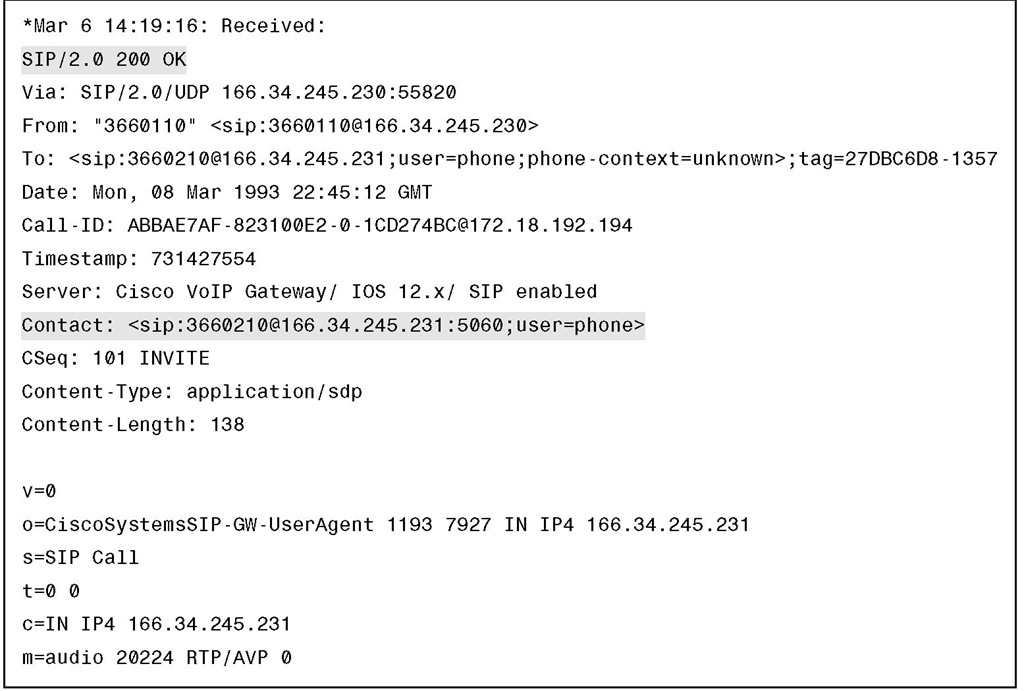
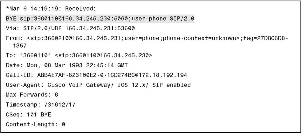
Examples 5-21, 5-22, and 5-23 show what a successful SIP session between two end- points looks like in the output of the debug ccsip messages command. Example 5-21 shows a SIP INVITE message being sent from one phone to another.
Example 5-21 INVITE Message
Example 5-22 shows the other endpoint returning an OK. Notice the Contact information added to the output.
Example 5-22 OK Message
Example 5-23 shows the other endpoint ending the session with a BYE message.
Example 5-23 BYE Message
Summary
The main topics covered in this topic are the following:
■ ITU-T Recommendation H.323 describes an infrastructure of terminals, common control components, services, and protocols that are used for multimedia communications.
■ Functional components of H.323 include terminals, gateways, gatekeepers, Cisco UBEs, and MCUs.
■ Calls can be established between endpoints, endpoints to gatekeepers, or gatekeepers to gatekeepers.
■ H.323 calls can occur with or without the use of a gatekeeper.
■ H.323 defines three types of multipoint conferences.
■ When configuring codecs, you can specify one codec or set up codec negotiation.
■ You might want to adjust some of the H.323 timers to meet network requirements.
■ You can use several commands to configure fax features on H.323 gateways.
■ DTMF relay solves the problem of DTMF distortion.
■ Use the show gateway command to verify H.323 gateway status.
■ MGCP defines an environment for controlling telephony gateways from a centralized call agent.
■ MGCP components include endpoints, gateways, and call agents.
■ Calls and connections are basic concepts in MGCP.
■ MGCP call flow consists of an exchange of messages between a call agent and a gateway.
■ The mgcp command can be used to configure residential and trunk gateways on a Cisco router.
■ Several show and debug commands help to verify an MGCP configuration.
■ SIP is defined by IETF RFCs 2543 and 3261 and allows integration with third-party VoIP networks.
■ SIP is modeled on the interworking of UAs and network servers.
■ A SIP call flow consists of signaling and transmission of bearer and media packets.
■ Communication between SIP components uses a request and response message model.
■ A SIP address consists of an optional user ID, a host description, and optional parameters to qualify the address more precisely.
■ SIP call setup models include direct, proxy server, and redirection.
■ You can use several commands on Cisco IOS to configure SIP on Cisco IOS routers.
■ You can use several commands on Cisco IOS to verify and troubleshoot a SIP integration.
![tmp1D-166_thumb[2][2] tmp1D-166_thumb[2][2]](http://what-when-how.com/wp-content/uploads/2012/03/tmp1D166_thumb22_thumb.png)
![tmp1D-167_thumb[2][2] tmp1D-167_thumb[2][2]](http://what-when-how.com/wp-content/uploads/2012/03/tmp1D167_thumb22_thumb.png)
![tmp1D-173_thumb[2][2] tmp1D-173_thumb[2][2]](http://what-when-how.com/wp-content/uploads/2012/03/tmp1D173_thumb22_thumb.png)

