SIP is one of the most important voice-signaling protocols within service provider VoIP networks and is supported by most IP telephony system vendors. As such, it is an ideal protocol for interconnecting different VoIP systems and networks. An understanding of the features and functions of SIP components and the relationships the components establish with each other is important in implementing a scalable, resilient, and secure SIP environment. This section describes how to configure SIP and explores the features and functions of the SIP environment, including its components, how these components interact, and how to accommodate scalability and survivability.
SIP Overview
SIP is an ASCII text-based application layer control protocol that can be used to establish, maintain, and terminate calls between two or more endpoints. SIP is an alternative protocol developed by the IETF for multimedia conferencing over IP. Its features are compliant with IETF RFC 2543, SIP: Session Initiation Protocol, published in March 1999, and IETF RFC 3261, SIP: Session Initiation Protocol, published in June 2002.
Many applications of the Internet require the creation and management of a session, where a session is considered an exchange of data between an association of participants. The implementation of these applications is complicated by the practices of participants: users might move between endpoints; they might be addressable by multiple names; and they might communicate in several different media. Numerous protocols have been authored that carry various forms of real-time multimedia session data such as voice, video, or text messages.
SIP works in concert with these protocols by enabling Internet endpoints (called user agents) to discover one another and to agree on a characterization of a session they would like to share. For locating prospective session participants, and for other functions, SIP enables the creation of an infrastructure of network hosts (called proxy servers) to which user agents can send registrations, invitations to sessions, and other requests.
SIP is not a standalone communications system. Rather, SIP is a component that can be used with other IETF protocols to build a complete multimedia architecture. These architectures include protocols such as RTP for transporting real-time data and providing QoS feedback, Real-time Streaming Protocol (RTSP) for controlling delivery of streaming media, MGCP for controlling gateways to the PSTN, and Session Description Protocol (SDP) for describing multimedia sessions. Therefore, SIP should be used in conjunction with other protocols to provide complete services to the users. However, the basic functionality and operation of SIP does not depend on any of these protocols.
SIP operates on the principle of session invitations based on an HTTP-like request/ response transaction model. Each transaction consists of a request that invokes a particular method or function on the server and at least one response. Through invitations, SIP initiates sessions or invites participants into established sessions. Descriptions of these sessions are advertised by any one of several means, including the Session Announcement Protocol (SAP) defined in RFC 2974, which incorporates a session description according to the SDP defined in RFC 2327.
SIP uses other IETF protocols to define other aspects of VoIP and multimedia sessions. For example, SIP uses URLs for addressing, DNS for service location, and Telephony Routing over IP (TRIP) for call routing.
Like other VoIP protocols, SIP is designed to address the functions of signaling and session management within a packet telephony network. Signaling allows call information to be carried across network boundaries. Session management provides the ability to control the attributes of an end-to-end call.
SIP supports five facets of establishing and terminating multimedia communications, resulting in the following capabilities:
■ Determines the location of the target endpoint: SIP supports address resolution, name mapping, and call redirection.
■ Determines the media capabilities of the target endpoint: SIP determines the lowest level of common services between the endpoints through SDP. Conferences are established using only the media capabilities that can be supported by all endpoints.
■ Determines the availability of the target endpoint: If a call cannot be completed because the target endpoint is unavailable, SIP determines whether the called party is connected to a call already or did not answer in the allotted number of rings. SIP then returns a message indicating why the target endpoint was unavailable.
■ Establishes a session between the originating and target endpoints: If the call can be completed, SIP establishes a session between the endpoints. SIP also supports midcall changes, such as the addition of another endpoint to the conference or the changing of a media characteristic or codec.
■ Handles the transfer and termination of calls: SIP supports the transfer of calls from one endpoint to another. During a call transfer, SIP establishes a session between the transferee and a new endpoint (specified by the transferring party) and terminates the session between the transferee and the transferring party. At the end of a call, SIP terminates the sessions among all parties.
How SIP Works
SIP is a simple, ASCII-based protocol that uses requests and responses to establish communication among the various components in the network and to ultimately establish a conference between two or more endpoints.
Users in a SIP network are identified by unique SIP addresses. A SIP address is similar to an e-mail address and is in the format of sip:userID@gateway.com. The user ID can be either a username or an E.164 address. The gateway can be either a domain (with or without a hostname) or a specific IP address.
Note An E.164 address is a telephone number with a string of decimal digits that uniquely indicates the public network termination point. The number contains the information necessary to route the call to this termination point.
Users register with a registrar server using their assigned SIP addresses. The registrar server provides this information to a location server upon request.
When a user initiates a call, a SIP request is sent to a SIP server (either a proxy or a redirect server). The request includes the address of the caller (in the From header field) and the address of the intended called party (in the To header field).
Over time, a SIP end user might move between end systems. The location of the end user can be dynamically registered with the SIP server. The location server can use one or more protocols (including finger, rwhois, and LDAP) to locate the end user. Because the end user can be logged in at more than one station and because the location server can sometimes have inaccurate information, it might return more than one address for the end user. If the request is coming through a SIP proxy server, the proxy server tries each of the returned addresses until it locates the end user. If the request is coming through a SIP redirect server, the redirect server forwards all the addresses to the caller in the Contact header field of the invitation response.
Why SIP
Several advantages exist to using SIP gateways as voice gateways:
■ Dial plan configuration directly on the gateway: This makes it possible, for example, to handle special calls, such as calls to directly connected analog devices, locally on the gateway without routing them to the Cisco Unified Communications Manager. Another scenario could be to route calls that are directed to other sites directly on the gateway without sending them to the local Cisco Unified Communications Manager cluster.
■ Translations defined per gateway: This makes it possible to meet regional requirements such as calling party transformations or special number formats. This also allows you to translate all incoming calls directly on the gateway to meet the internally used number format and then process calls with only those internal numbers on the Cisco Unified CallManager clusters within the network.
■ Advanced support of third-party telephony systems: Because SIP is the most widely used standard within VoIP systems of different vendors and has many features included as non-proprietary functions, using a SIP gateway enables you to integrate third-party telephony systems.
■ Interoperability with third-party voice gateways: Most third-party voice gateways support SIP. Therefore, using SIP would be the most feasible way to connect a Cisco IOS voice gateway to a third-party voice gateway, rather then by using another VoIP signaling protocol.
SIP Architecture
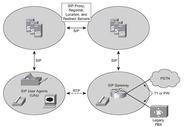
SIP is a peer-to-peer protocol. Figure 5-23 offers an example of a SIP network.
Figure 5-23 SIP Architecture
The peers in a session are called user agents (UA). A user agent can function in one of two roles:
■ User agent client (UAC): A client application that initiates a SIP request
■ User agent server (UAS): A server application that contacts the user when a SIP invitation is received and then returns a response on behalf of the user to the invitation originator
Typically, a SIP UA can function as a UAC or a UAS during a session, but not both in the same session. Whether the endpoint functions as a UAC or a UAS depends on the UA that initiated the request. The initiating UA uses a UAC, and the terminating UA uses a UAS.
From an architectural standpoint, the physical components of a SIP network are grouped into two categories:
■ Clients (endpoints)
■ Servers
Clients (endpoints) include the following:
■ Phone: An IP telephone acts as a UAS or UAC on a session-by-session basis.
■ Software telephones and Cisco SIP IP Phones initiate SIP requests and respond to requests.
■ ephones are IP phones that are not configured on the gateway.
■ Gateway: A gateway acts as a UAS or UAC and provides call control support. Gateways provide many services, the most common being a translation function between SIP conferencing endpoints and other terminal types. This function includes translation between transmission formats and between communications procedures. A gateway also translates between audio and video signals and performs call setup and clearing on both the IP side and the SCN side.
Servers include the following:
■ Proxy server: An intermediate component that receives SIP requests from a client, and then forwards the requests on behalf of the client to the next SIP server in the network. The next server can be another proxy server or a UAS. Proxy servers can provide functions such as authentication, authorization, network access control, routing, reliable request transmissions, and security.
■ Redirect server: Provides the client with information about the next hop or hops that a message should take, and then the client contacts the next-hop server or UAS directly. The UA redirects the invitation to the server identified by the redirect server. The server can be another network server or a UA.
■ Registrar server: Receives requests from UACs for registration of their current location. Registrar servers are often located near or even collocated with other network servers, most often a location server.
■ Location server: An abstraction of a service providing address resolution services to SIP proxy or redirect servers. A location server embodies mechanisms to resolve addresses. These mechanisms can include a database of registrations or access to commonly used resolution tools such as Finger protocol, RWhois, LDAP, or operating system-dependent mechanisms. A registrar server can be modeled as one subcomponent of a location server. The registrar server is partly responsible for populating a database associated with the location server.
Note In addition, the SIP servers can interact with other application services, such as LDAP servers, location servers, a database application, or an extensible markup language (XML) application. These application services provide back-end services, such as directory, authentication, and billing services.
SIP Call Flow
The call flows between SIP gateways can be direct or through a proxy or redirect server.
Direct Call Setup
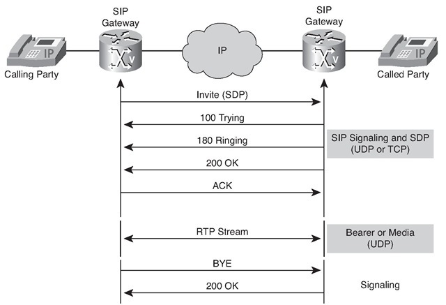
When a UA recognizes the address of a terminating endpoint from cached information, or has the capacity to resolve it by some internal mechanism, the UAC might initiate direct (UAC-to-UAS) call setup procedures. If a UAC recognizes the destination UAS, the client communicates directly with the server, as illustrated in Figure 5-24. In situations in which the client is unable to establish a direct relationship, the client solicits the assistance of a network server.
Figure 5-24 Direct Call Setup
Figure 5-24 illustrates the following steps of a direct call setup procedure:
1. The originating UAC sends an invitation (INVITE) to the UAS of the recipient. The message includes an endpoint description of the UAC and SDP.
2. If the UAS of the recipient determines that the call parameters are acceptable, it responds positively to the originator UAC.
3. The originating UAC issues an ACK.
At this point, the UAC and UAS have all the information that is required to establish RTP sessions between them.
Call Setup Using a Proxy Server
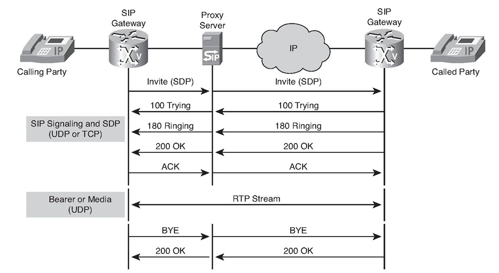
The proxy server procedure is transparent to a UA. The proxy server intercepts and forwards an invitation to the destination UA on behalf of the originator, as depicted in Figure 5-25.
Figure 5-25 Call Setup Using a Proxy Server
A proxy server responds to the issues of the direct method by centralizing control and management of call setup and providing a more dynamic and up-to-date address resolution capability. The benefit to the UA is that it does not need to learn the coordinates of the destination UA, yet it can still communicate with the destination UA. The disadvantages of this method are that using a proxy server requires more messaging and creates a dependency on the proxy server. If the proxy server fails, the UA is incapable of establishing its own sessions.
Note Although the proxy server acts on behalf of a UA for call setup, the UAs establish RTP sessions directly with each other.
When a proxy server is used, the call setup procedure, as illustrated in Figure 5-25, uses the following steps:
1. The originating UAC sends an invitation (INVITE) to the proxy server.
2. The proxy server, if required, consults the location server to determine the path to the recipient and its IP address.
3. The proxy server sends the INVITE to the UAS of the recipient.
4. If the UAS of the recipient determines that the call parameters are acceptable, it responds positively to the proxy server.
5. The proxy server responds to the originating UAC.
6. The originating UAC issues an ACK.
7. The proxy server forwards the ACK to the recipient UAS.
The UAC and UAS now have all the information that is required to establish RTP sessions between them.


