Media Flow and Transparent Codec Commands
To configure media flow-through or media flow-around, use the following media command:
Note that this command can be issued in dial-peer configuration mode or globally under the voice service configuration mode. The default is media flow-through.
To configure transparent codec pass-through, use the following codec transparent command:
Note that this command can be issued in dial-peer configuration mode or via a codec class.
Configuring Transparent Codec Pass-Through and Media Flow-Around
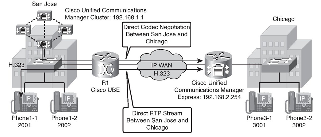
Figure 9-17 shows a sample scenario used to configure H.323-to-H.323 interworking, including transparent codec pass-through and media flow-around, using a Cisco UBE router. The Cisco Unified Communications Manager cluster in San Jose is connected with the Cisco Unified Communications Manager Express router in Chicago using a Cisco UBE router. Codec negotiation is performed directly between the Cisco Unified Communications Manager cluster and the Cisco Unified Communications Manager Express router, and RTP streams flow directly between the endpoints.
Figure 9-17 Transparent Codec Pass-Through and Media Flow-Around Example Topology
Codec transparency enables a Cisco UBE router to pass codec capabilities between end-points. If you configure transparency, a Cisco UBE router uses the codec that was specified by the endpoints for setting up a call. To enable endpoint-to-endpoint codec negotiation without a Cisco UBE router, use the codec transparent command.
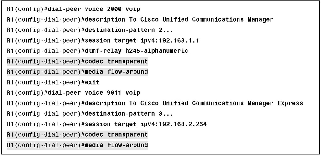
With the default configuration, a Cisco UBE router receives media packets from the inbound call leg, terminates them, and then reoriginates the media stream on an outbound call leg. Media flow-around enables media packets to be passed directly between the endpoints, without the intervention of a Cisco UBE router. The Cisco UBE router continues to handle routing and billing functions. Media flow-around for SIP-to-SIP calls is not supported. Use the media flow-around command to enable media flow-around. Example 9-6 illustrates the use of both the codec transparent and the media flow-around commands.
Example 9-6 Transparent Codec Pass-Through and Media Flow-Around Configuration
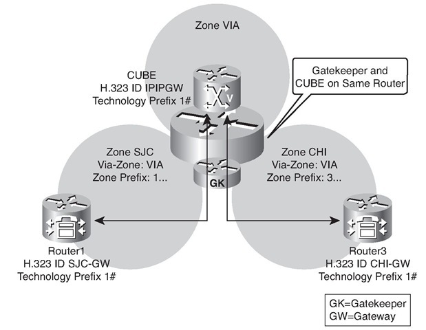
Figure 9-18 shows a sample scenario used to configure a Cisco UBE router and a via-zone gatekeeper. A gatekeeper is configured with two standard local zones: San Jose (SJC) and Chicago (CHI). The Cisco Unified Communications Manager Express Router1 is registered in the SJC zone, and the Cisco Unified Communications Manager Express Router3 is registered in CHI zone. Calls between Chicago and San Jose should be routed by the gatekeeper. Instead of routing calls directly between the two zones, the gatekeeper should route the calls through the VIA, which includes a Cisco UBE router.
Configuring Cisco UBEs and Via-Zone Gatekeepers
Figure 9-18 shows a sample scenario used to configure a Cisco UBE router and a via-zone gatekeeper. A gatekeeper is configured with two standard local zones: San Jose (SJC) and Chicago (CHI). The Cisco Unified Communications Manager Express Router1 is registered in the SJC zone, and the Cisco Unified Communications Manager Express Router3 is registered in CHI zone. Calls between Chicago and San Jose should be routed by the gatekeeper. Instead of routing calls directly between the two zones, the gatekeeper should route the calls through the VIA, which includes a Cisco UBE router.
Note The Cisco UBE function and the gatekeeper function are performed by the same router.
Configure the Gatekeeper
You can complete these steps to configure a gatekeeper:
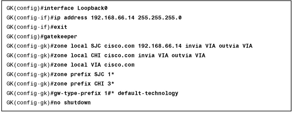
Step 1. Create a loopback interface to use for the gatekeeper.
Step 2. Create local, remote, and VIA zones.
Two local zones, SJC and CHI, are configured, but instead of configuring a standard local zone, the invia and outvia options are used to route calls to and from the zones using the VIA zone.
In addition to the SJC and CHI local zones, another local via-zone is configured. This zone will contain the Cisco UBE router.
Figure 9-18 Cisco UBEs and Via-Zone Gatekeepers Configuration Topology
Step 3. Specify zone and technology prefixes.
Standard zone prefix routing is set up, and the default technology 1# is configured. Example 9-7 illustrates a sample via-gatekeeper configuration.
Example 9-7 Via-Zone Gatekeeper Configuration
Configure the Cisco UBE
After the gatekeeper configuration is done, the Cisco UBE configuration is performed on the same router.
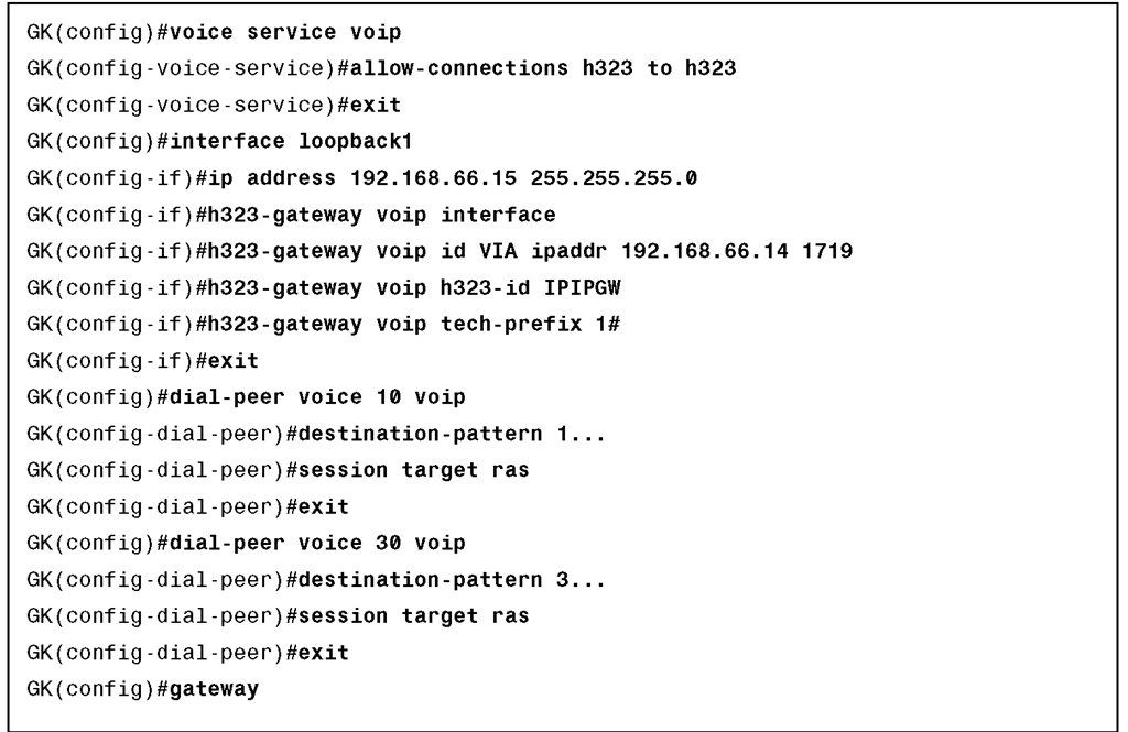
You can complete these steps to configure the Cisco UBE feature: Step 1. Enable H.323 interworking.
Step 2. Create a loopback interface to use as the source interface for Cisco UBE to register with the gatekeeper.
The Loopback1 interface is used as the H.323 gateway interface. The Cisco UBE router will register in zone VIA with the H.323 ID CUBE and the technology prefix 1#.
Step 3. Create two dial peers—one pointing to San Jose and the other to Chicago.
Step 4. Enable the gateway process.
Example 9-8 illustrates a sample Cisco UBE configuration.
Example 9-8 Cisco UBE Configuration
Verifying Cisco UBEs and Via-Zone Gatekeepers
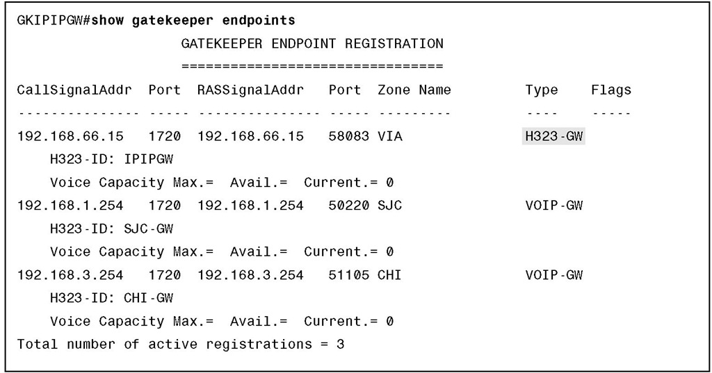
When you use the show gatekeeper endpoints command on the gatekeeper, a Cisco UBE router will be displayed as an H323-GW type. In the output shown in Example 9-9, the Cisco UBE router is registered using the Loopback1 IP address 192.168.66.15.
Example 9-9 Verifying Cisco UBEs and Via-Zone Gatekeepers with the show gatekeeper endpoints Command
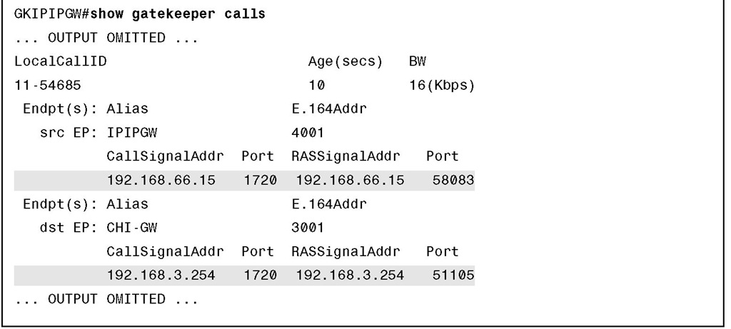
When a call is active, the show gatekeeper calls command will display two call legs. The first call leg, as illustrated in Figure 9-19 and Example 9-10, is between the originating gateway (Router1 in this case) and the Cisco UBE router.
Figure 9-19 Verifying Cisco UBEs and Via-Zone Gatekeepers Topology—Call Leg 1
Example 9-10 Verifying Cisco UBEs and Via-Zone Gatekeepers with the show gatekeeper calls Command—Call Leg 1
Example 9-10 Verifying Cisco UBEs and Via-Zone Gatekeepers with the show gatekeeper calls Command—Call Leg 1 continued
The second call leg, as illustrated in Figure 9-20 and Example 9-11, is between the Cisco UBE router and the terminating gateway (Router3 in this case).
Figure 9-20 Verifying Cisco UBEs and Via-Zone Gatekeepers Topology—Call Leg 2
Example 9-11 Verifying Cisco UBEs and Via-Zone Gatekeepers with the show gatekeeper calls Command—Call Leg 2
Summary
The main topics covered in this topic are the following:
■ Cisco UBE routers interconnect multiple VoIP networks by routing calls between two VoIP dial peers.
■ Features include protocol interworking, address hiding, codec filtering, and video interworking.
■ Protocol interworking interconnects VoIP networks, using the same or different signaling protocols.
■ Media streams can flow through or bypass a Cisco UBE router.
■ Cisco UBE routers use standard Cisco IOS codec negotiations to influence negotiations between VoIP networks.
■ Cisco UBE routers can use RSVP to implement CAC, for example, between Cisco Unified Communications Manager clusters.
■ Cisco UBE routers can register with gatekeepers and be used as a standard gateway or with via-zones.
■ Cisco UBE call flow depends on network topology and features implemented.
■ Protocol interworking is configured using the allow-connection command.
■ H.323-to-H.323 interworking is configured using the allow-connection h323 to h323 command.
■ H.323-to-SIP interworking is configured using the allow-connection h323 to sip command.
■ Media flow-through or flow-around can be configured globally or per dial peer.
■ Ensure that the inbound and outbound dial peers have matching media and codec configurations.
■ Cisco UBE routers can be used in conjunction with gatekeepers by registering them in a via-zone.
■ A gatekeeper will show two call legs when using a Cisco UBE router.

